
Additive manufacturing systems and methods

a manufacturing system and additive technology, applied in the field of additive manufacturing, can solve the problems of difficult to achieve optimal melting/solidification rate, inability to control the desired grain size and morphology with traditional techniques, and the inability to implement additively manufactured components, etc., to achieve the effect of reducing the cross-sectional area of the weld pool and reducing the wall thickness of the additively manufactured articl

Inactive Publication Date: 2017-04-20
DELAVAN
View PDF2 Cites 18 Cited by
  • Summary
  • Abstract
  • Description
  • Claims
  • Application Information

AI Technical Summary

Benefits of technology

This patent is about controlling the shape of a weld pool when welding materials using additive manufacturing. This can be done by reducing the size of the weld pool to make the wall of the article thinner. Additionally, the patent is about controlling the flow rate of the molten metal within the weld pool. This can help to improve the quality and strength of the weld.

Problems solved by technology

There are many challenges in the Powder Bed Fusion and Direct Energy Deposition technologies that prevent additively built components from being implemented for demanding applications.
For example the desired grain size and morphology is not controllable with traditional techniques.
Another challenge is that optimal melting / solidification rates are difficult to achieve.
Depending on alloy composition and part cross section the solidification rate difference may produce undesirable phases, microstructure defects, and excessive thermal stresses.
In certain cases, precursor material is difficult to segregate from alloying elements.
Additionally, weld pool melt velocities create strong molten metal turbulence that leads to spattering and melt ejections.
Further, molten metal surface tension affects weld pool geometry.

Method used


Image

  • Additive manufacturing systems and methods
  • Additive manufacturing systems and methods
  • Additive manufacturing systems and methods

Examples


Embodiment Construction

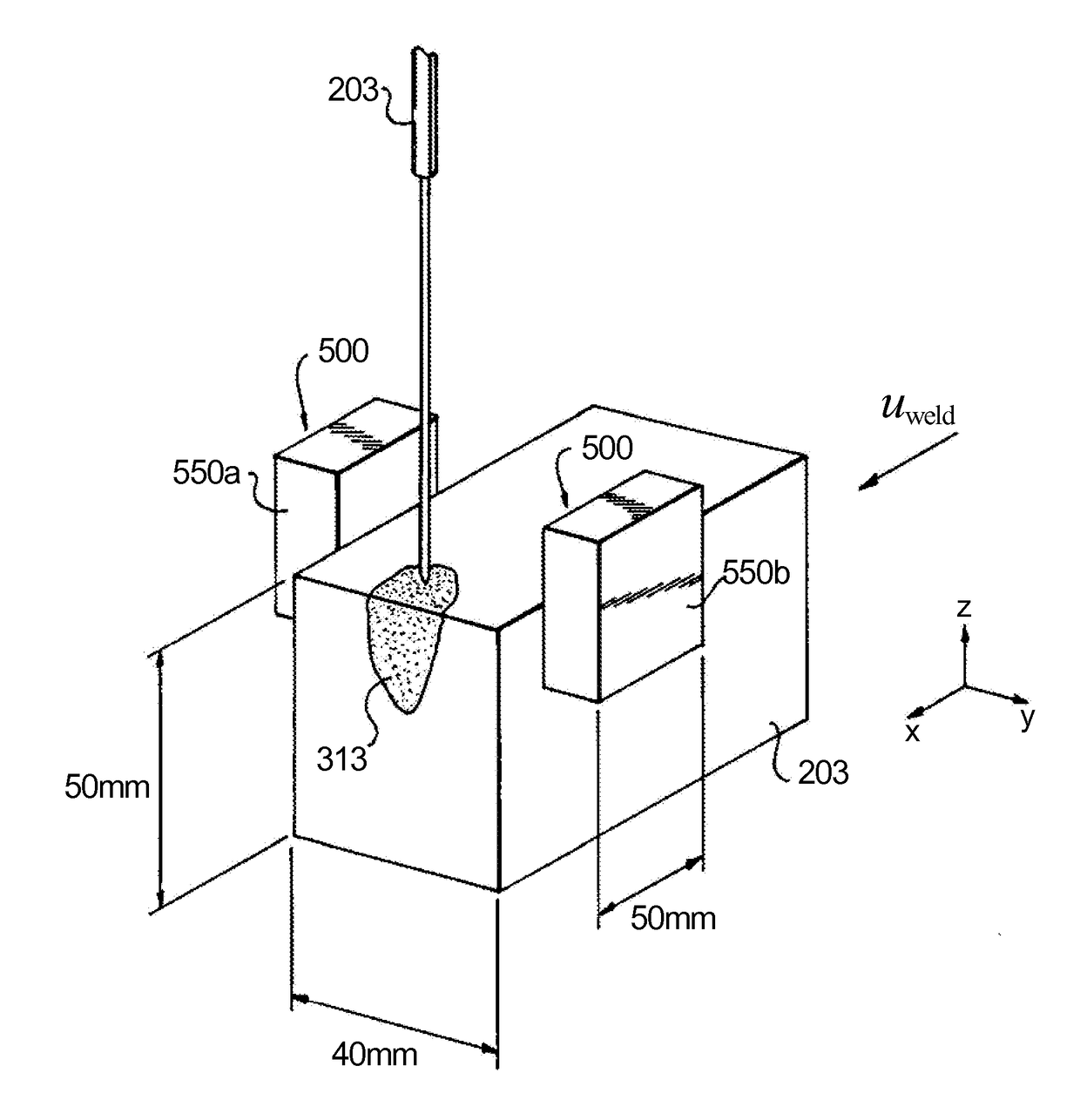
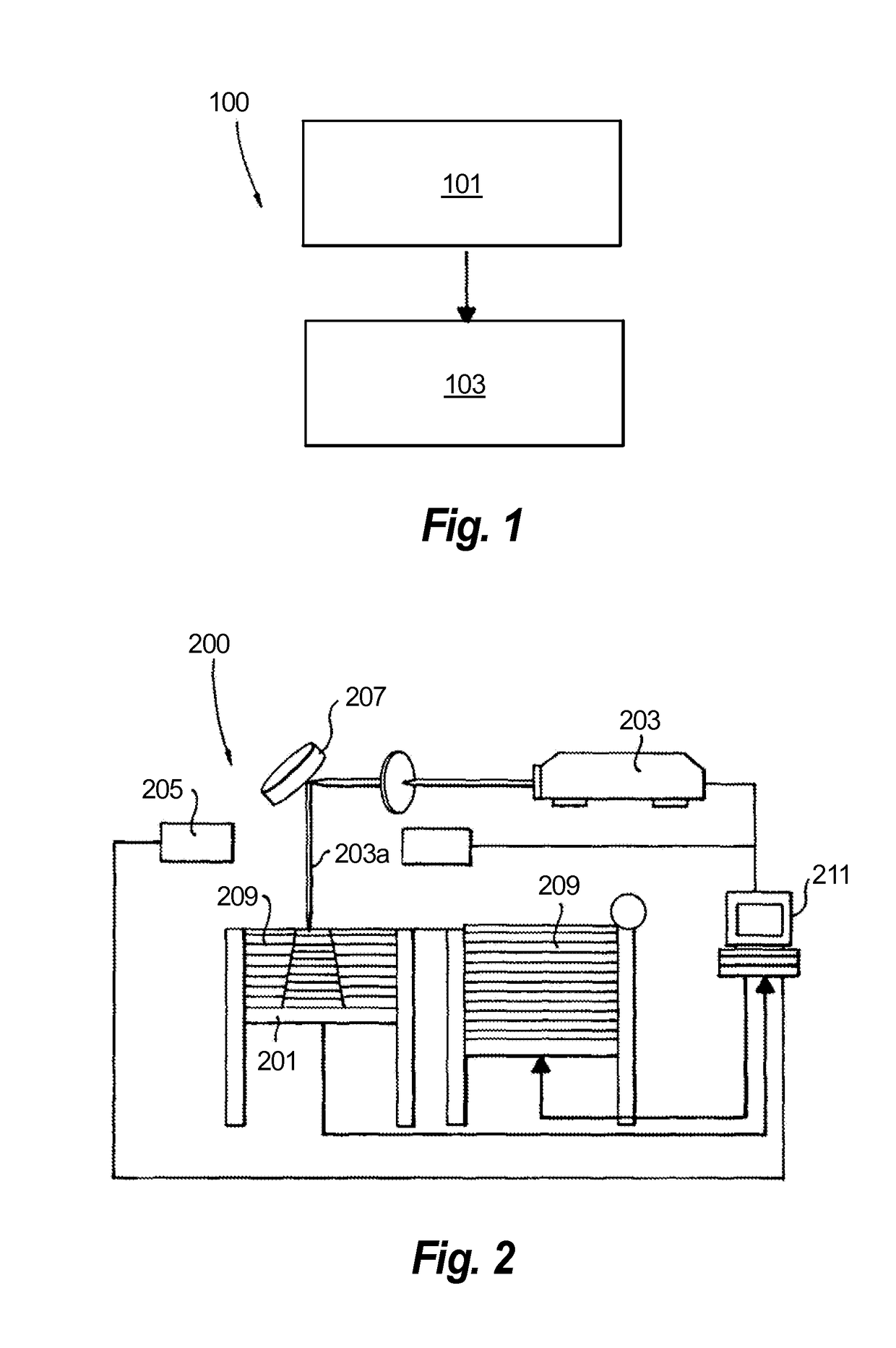
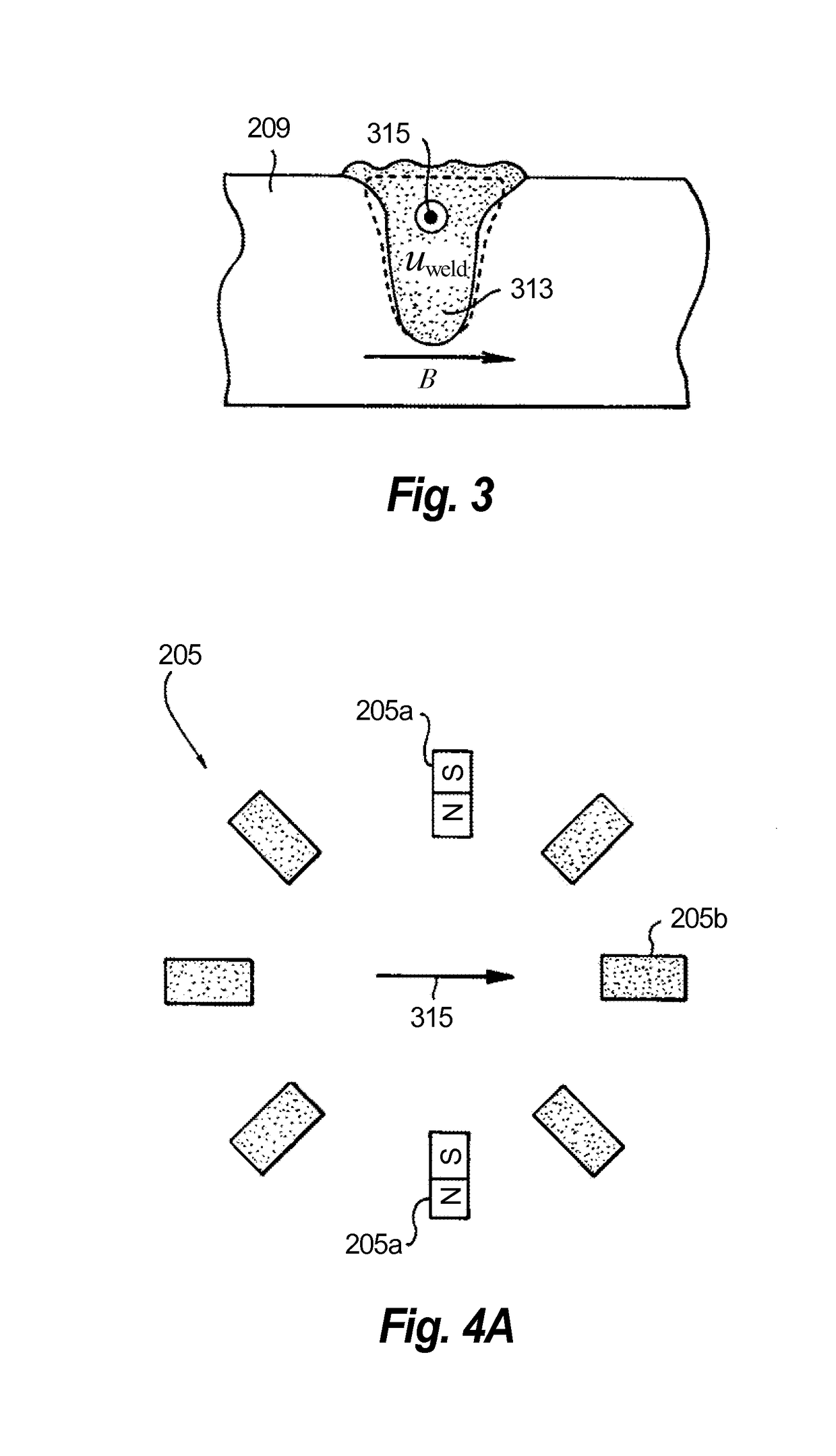
[0028]Reference will now be made to the drawings wherein like reference numerals identify similar structural features or aspects of the subject disclosure. For purposes of explanation and illustration, and not limitation, an illustrative view of an embodiment of a method in accordance with the disclosure is shown in FIG. 1 and is designated generally by reference character 100. Other embodiments and / or aspects of this disclosure are shown in FIGS. 2-5. The systems and methods described herein can be used to improve manufacturing characteristics and the quality of additively manufactured articles.

[0029]Referring to FIGS. 1-3, a method 100 for additively manufacturing an article includes applying 101 energy to a powder 209 to produce a weld pool 313 of molten powder and applying 103 an electromagnetic field to the weld pool 313 to control one or more characteristics of the weld pool 313. Applying the electromagnetic field 103 can include applying an electric field and / or a magnetic fi...


PUM

PropertyMeasurementUnit
energyaaaaaaaaaa
electromagnetic fieldaaaaaaaaaa
electric fieldaaaaaaaaaa

Abstract

A method for additively manufacturing an article includes applying energy to a powder to produce a weld pool of molten powder and applying an electromagnetic field to the weld pool to control one or more characteristics of the weld pool. Applying the electromagnetic field can include applying an electric field and / or a magnetic field to the weld pool.

Description

BACKGROUND[0001]1. Field[0002]The present disclosure relates to additive manufacturing, more specifically to techniques and systems for additive manufacturing processes (e.g., powder bed fusion and direct energy deposition for building or repairing metal parts).[0003]2. Description of Related Art[0004]Traditionally, some main criteria for selection of powdered alloys for additive manufacturing are weldability, propensity to form a stable weld pool without keyhole porosity, and absence of defects during the solidification process. In addition to these criteria, other very important technological aspects of the fusion process also need to be considered because they can affect the material microstructure evolution.[0005]There are many challenges in the Powder Bed Fusion and Direct Energy Deposition technologies that prevent additively built components from being implemented for demanding applications. For example the desired grain size and morphology is not controllable with traditiona...

Claims


Application Information

Patent Timeline
Patent Type & Authority Applications(United States)
IPC IPC(8): B23K26/70B23K26/10B22F3/105B23K26/342
CPCB23K26/702B23K26/342B23K26/10B22F2202/06B22F2003/1056B22F2202/05B22F3/1055B22F2007/068B22F2999/00B33Y10/00B33Y30/00B23K26/082B29C64/106B29C64/153B29C64/35B29C64/209B29C64/364B23K2103/04B23K2103/10B23K2103/42B23K2103/50B29C64/268Y02P10/25B22F12/00B22F12/224B22F10/38B22F10/28B22F10/25B22F12/17B22F2203/11
Inventor MIRONETS, SERGEYSTAROSELSKY, ALEXANDERMARTIN, THOMAS J.
Owner DELAVAN
Learn More