
Battery cooling system for a vehicle

a battery cooling and vehicle technology, applied in vehicle heating/cooling devices, electric generators, transportation and packaging, etc., can solve the problems of deteriorating riding comfort of the vehicle, complicated battery cooling system from the inside of the engine room, and increased size and weight of a cooling module disposed in the front portion of the vehicle, so as to achieve optimal performance, effectively warmed up and cooled down, and simplified the whole system

Active Publication Date: 2017-04-20
HYUNDAI MOTOR CO LTD +1
View PDF1 Cites 43 Cited by
  • Summary
  • Abstract
  • Description
  • Claims
  • Application Information

AI Technical Summary

Benefits of technology

The battery cooling system for electric or hybrid vehicles described in this patent simplifies the cooling system for the battery by integrating a heat pump system with a cooling system for the electric device. This enables effective warming and cooling of the battery based on the vehicle mode, leading to optimal battery performance and increased driving distance. Additionally, the system reduces manufacturing costs and weight, improves space utilization, and reduces the complexity of the overall system.

Problems solved by technology

Thus, the size and weight of a cooling module disposed in a front portion of the vehicle are increased, and layouts for connection wires through which a refrigerant or a coolant is supplied to the heat pump system, the cooling means, and the battery cooling system from the inside of an engine room are complicated.
Further, for optimal performance of the battery, a battery cooling system that warms up or cools down the battery according to a state of the vehicle is separately provided, and thus a plurality of valves are provided for connection with the respective connection wires and noise and vibration caused from frequent opening / closing of the valves is transferred to the inside of the vehicle, thereby deteriorating riding comfort of the vehicle.

Method used


Image

  • Battery cooling system for a vehicle
  • Battery cooling system for a vehicle
  • Battery cooling system for a vehicle

Examples


Embodiment Construction

[0050]Reference will now be made in detail to various embodiments of the present invention(s), examples of which are illustrated in the accompanying drawings and described below. While the invention(s) will be described in conjunction with exemplary embodiments, it will be understood that the present description is not intended to limit the invention(s) to those exemplary embodiments. On the contrary, the invention(s) is / are intended to cover not only the exemplary embodiments, but also various alternatives, modifications, equivalents and other embodiments, which may be included within the spirit and scope of the invention as defined by the appended claims.

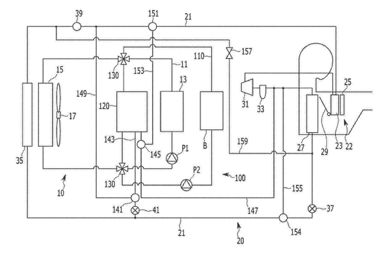
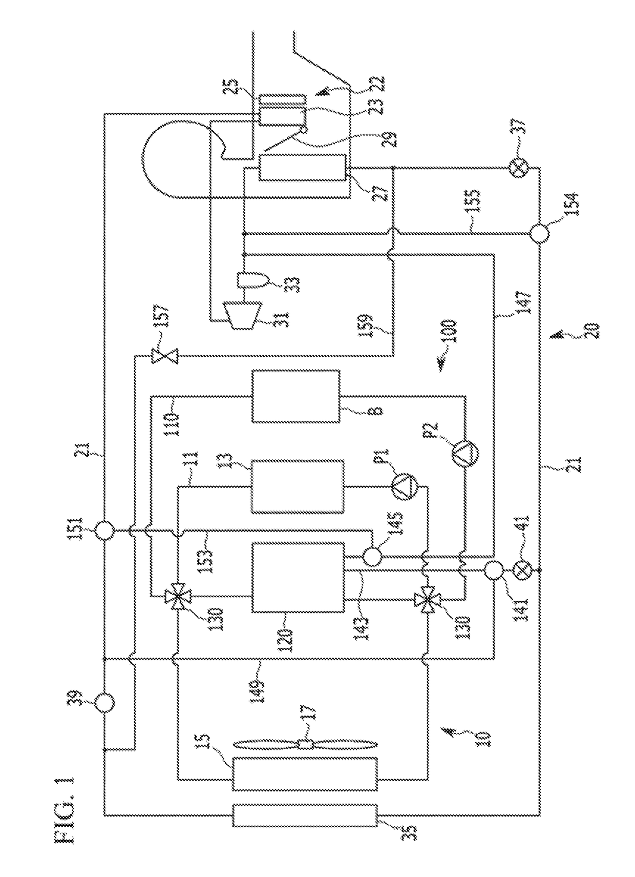
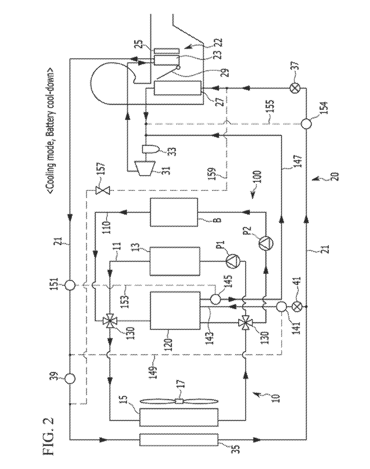
[0051]FIG. 1 is a block diagram of a battery cooling system for a vehicle according to various embodiments of the present invention. A battery cooling system 100 for a vehicle according to various embodiments of the present invention is applicable to an electric vehicle or a fuel cell vehicle equipped with a cooling system 10 for ...


PUM


Abstract

A battery cooling system for a vehicle, to warm up or cool down a battery installed in the vehicle by selectively using a refrigerant and a coolant according to a mode of the vehicle may include a heat exchanger, connected with a refrigerant line of a heat pump system through first and second connection lines, connected with a cooling line of a cooling system for an electric device through a battery cooling line, and configured to selectively eat-exchange between the coolant and refrigerant introduced into the heat exchanger, two first valves disposed in the battery cooling line with the heat exchanger disposed therebetween, and selectively connecting the cooling line and the battery cooling line, a first branch line connected with the refrigerant line through a second valve, and a second branch line selectively connecting the refrigerant line and the second connection line through a third valve and a fourth valve.

Description

CROSS-REFERENCE TO RELATED APPLICATION[0001]The present application claims priority to Korean Patent Application No. 10-2015-0145630 filed Oct. 19, 2015, the entire contents of which is incorporated herein for all purposes by this reference.BACKGROUND OF THE INVENTION[0002]Field of the Invention[0003]The present invention relates to a battery cooling system for a vehicle. More particularly, the present invention relates to a battery cooling system that makes a heat pump system and a cooling system for an electric device, circulating a coolant to the electric device including a motor integrated with each other in an electric vehicle or a hybrid vehicle, and warming up or cooling down a battery using a refrigerant and a coolant according to a mode of the vehicle.[0004]Description of Related Art[0005]In general, an air conditioning device for a vehicle includes an air conditioning system that circulates a refrigerant to heat or cool the inside of the vehicle.[0006]Such an air condition...

Claims


Application Information

Patent Timeline
Patent Type & Authority Applications(United States)
IPC IPC(8): B60H1/32B60H1/00
CPCB60H1/3205B60H1/004B60H1/00392B60H1/00428H01M10/613H01M10/615H01M10/625H01M10/6567H01M10/663B60H1/00278B60H1/00921B60H2001/00307B60H2001/00928B60H1/32281Y02T10/70Y02E60/10
Inventor KIM, JAE YEONLEE, HAE JUN
Owner HYUNDAI MOTOR CO LTD
Learn More