Eureka AIR delivers breakthrough ideas for toughest innovation challenges, trusted by R&D personnel around the world.

Four-cycle ohv engine

Active Publication Date: 2017-04-20
SUZUKI MOTOR CO LTD
View PDF14 Cites 2 Cited by
  • Summary
  • Abstract
  • Description
  • Claims
  • Application Information

AI Technical Summary

Benefits of technology

The present invention aims to solve problems with traditional four-cycle OHV engines by making them more compact and easy to lubricate. The technical effects of this invention include improved engine performance, better fuel efficiency, and improved oil flow.

Problems solved by technology

This makes the lubricating oil passage complicated.
The lubricating oil passage for the camshaft is additionally required, and this makes the size of the engine large especially in the width direction.
Accordingly, it has been an actual condition that such as downsizing of the engine is actually difficult.

Method used


Image

  • Four-cycle ohv engine
  • Four-cycle ohv engine
  • Four-cycle ohv engine

Examples


Embodiment Construction

[0025]The following describes preferred embodiments of a four-cycle OHV engine according to the present invention based on the drawings.

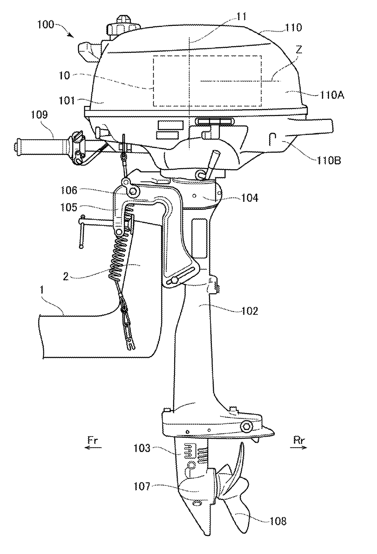
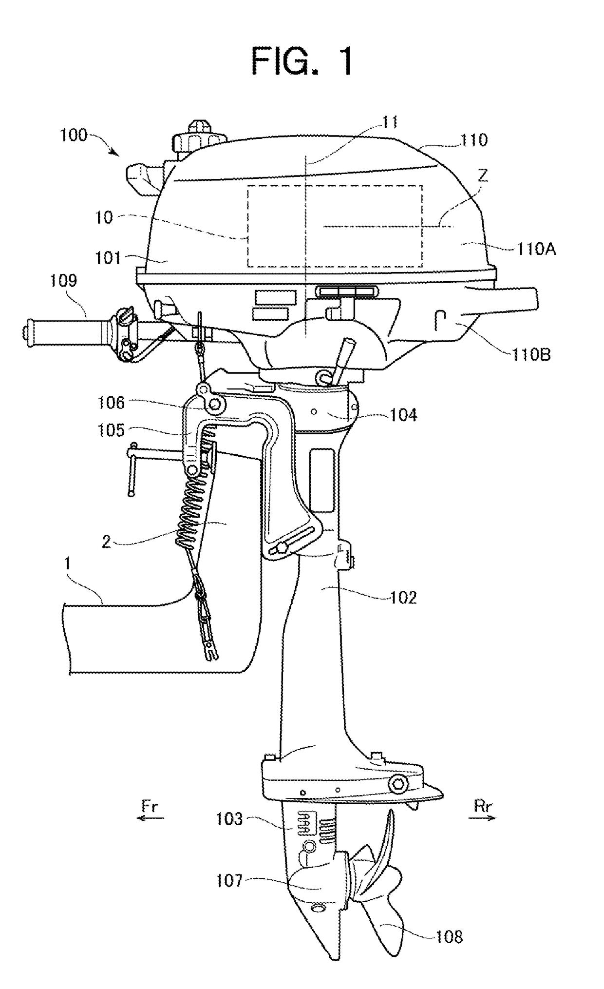
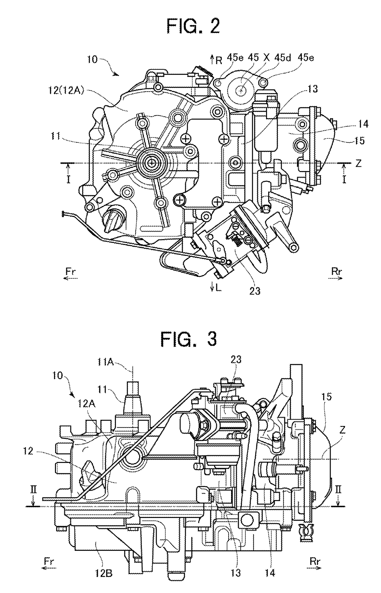
[0026]FIG. 1 is a left side view illustrating an exemplary schematic configuration of an outboard motor 100 as an application example of the present invention. In this example, as illustrated in FIG. 1, the outboard motor 100 is secured to a rear plate 2 of a ship 1 on a front portion side of the outboard motor 100. The outboard motor 100 mounts an engine 10 according to the present invention. In the following description, in each drawing, an arrow Fr and an arrow Rr indicate forward and rearward of the outboard motor 100 or the engine 10 respectively, and an arrow R and an arrow L indicate the right side and the left side of the side portion of the outboard motor 100 respectively, as necessary.

[0027]In an overall configuration of the outboard motor 100, an upper unit (or power unit) 101, a middle unit 102 and a lower unit 103 are configured to be l...


PUM


Abstract

The oil filter device is disposed on a side portion of one side of a cylinder body in a width direction in a cylinder head side with respect to an engine case in a space between center lines of main lubricating oil passages and a cylinder axis line of the cylinder body, and includes an oil pump disposed on the engine case and further lubricating oil passages that connect to the main lubricating oil passage.

Description

CROSS-REFERENCE TO RELATED APPLICATIONS[0001]This application is based upon and claims the benefit of priority of the prior Japanese Patent Application No. 2015-206703, filed on Oct. 20, 2015, the entire contents of which are incorporated herein by reference.BACKGROUND OF THE INVENTION[0002]Field of the Invention[0003]The present invention relates to a four-cycle OHV engine appropriate for such as an outboard motor that includes an internal combustion engine as a power source.[0004]Description of the Related Art[0005]In what is called a vertical engine where a crankshaft is vertically disposed, a lubricating system including an oil pump to pump lubricating oil includes a lubricating oil passage to circulate the lubricating oil. The lubricating system includes an oil filter, a drive mechanism of an oil pump and similar unit, and these units are connected to one another via a lubricating oil passage.[0006]For example, in an engine disclosed in Patent Document 1, a main shaft of an oil...

Claims


Application Information

Patent Timeline
IPC IPC(8): F01M11/03F02B75/00F01M1/02F01L1/047F01M11/02F01M11/00F02M35/10F02B75/02F01M1/10
CPCF01M11/03F02B75/02F02B75/007F01M1/02F01M1/10F01M2011/026F01M11/0004F02M35/1015F01L1/047F02B2075/027F01M11/02
Inventor NAKAMURA, HIDETOISHIHARA, YASUOMI
Owner SUZUKI MOTOR CO LTD
Why Eureka
Eureka Blog
Learn More