Magnetic field sensing apparatus

a technology of magnetic field and sensing apparatus, which is applied in the direction of magnetic field measurement using permanent magnets, instruments, pulse techniques, etc., can solve the problems of complex overall manufacturing process, difficult to reduce manufacturing costs, and difficult use, and achieves simplified structure and small volume

Active Publication Date: 2017-04-20
ISENTEK INC
View PDF7 Cites 7 Cited by
  • Summary
  • Abstract
  • Description
  • Claims
  • Application Information

AI Technical Summary

Benefits of technology

[0010]In the magnetic field sensing apparatus of the embodiment of the invention, the magnetic flux concentrator is used to cause the magnetic field components in the three different directions to bend to directions that can be sensed by the magnetoresistance units, and the magnetic field components in the three different directions, after being bent, have three different combinations of directions passing through the magnetoresistance units. As a result, by electrically connecting the magnetoresistance units to form the at least one kind of Wheatstone full bridge in the three different periods, the magnetic field components in the three different directions can be respectively measured, and the at least one kind of Wheatstone full bridge can respectively output the three signals corresponding to the magnetic field components in the three different directions. Accordingly, the magnetic field sensing apparatus in the embodiment of the invention can have a simplified structure while simultaneously achieving a triaxial magnetic field measurement, and thus can further have a smaller volume.

Problems solved by technology

As a result, when the user rotates the portable electronic device to a different angle, the detection sensitivities with respect to a same magnetic field are different, thereby causing distress in the use.
In the conventional technology, in order to achieve a multi-axis sensing of the magnetic field, more than two times of manufacturing process are usually used, that is, using manufacturing processes of more than two wafers to manufacture a multi-axial magnetic field sensing module, and thus the overall manufacturing process is complicated and the manufacturing cost is difficult to be lowered.
In addition, this also causes the magnetic field sensing apparatus difficult to be further minimized.

Method used


Image

  • Magnetic field sensing apparatus
  • Magnetic field sensing apparatus
  • Magnetic field sensing apparatus

Examples


Embodiment Construction

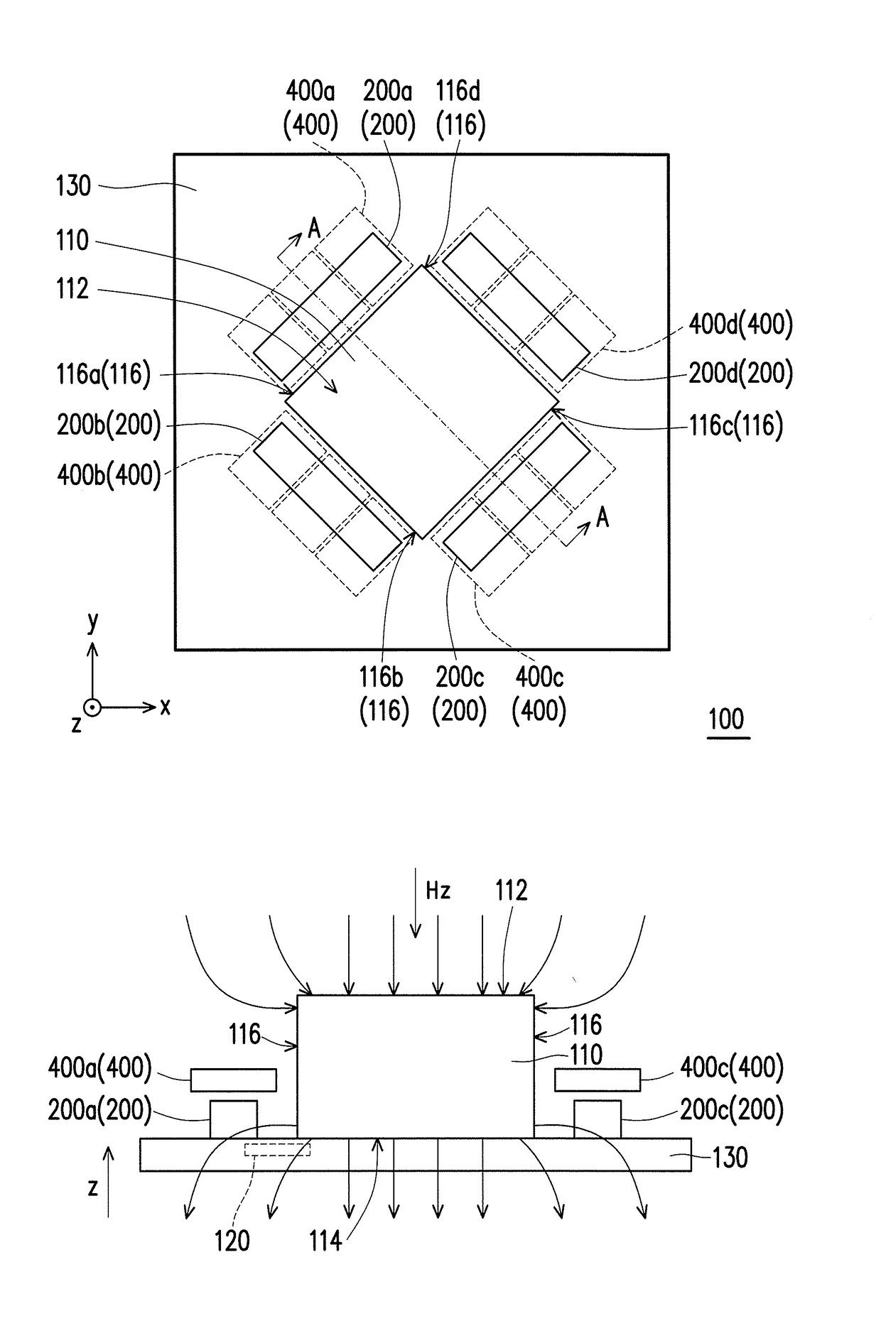
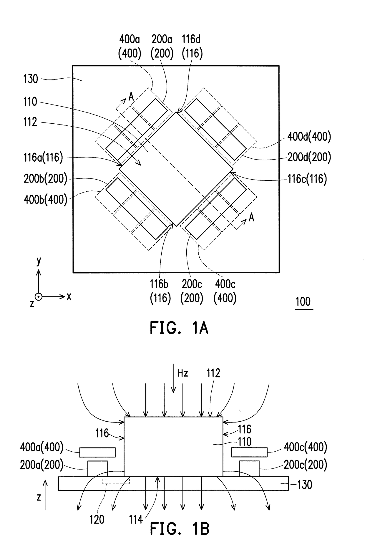
[0028]FIG. 1A is a schematic top view illustrating a magnetic field sensing apparatus according to an embodiment of the invention, and FIG. 1B is a schematic cross-sectional view of the magnetic field sensing apparatus of FIG. 1A along a line A-A. Referring to FIG. 1A and FIG. 1B, the magnetic field sensing apparatus 100 of the present embodiment includes a magnetic flux concentrator 110 and a plurality of magnetoresistance units 200. The magnetic flux concentrator 110 has a top surface 112, a bottom surface 114 opposite to the top surface 112 (as shown in FIG. 1B), and a plurality of side surfaces 116 connecting the top surface 112 and the bottom surface 114, and the magnetoresistance units 200 are respectively disposed beside the side surfaces 116.

[0029]In the present embodiment, a material of the magnetic flux concentrator 110 includes a ferromagnetic material with a magnetic permeability greater than 10. In addition, a residual magnetism of the magnetic flux concentrator 110 is,...


PUM


Abstract

A magnetic field sensing apparatus including a magnetic flux concentrator and a plurality of magnetoresistance units is provided. The magnetic flux concentrator has a top surface, a bottom surface opposite to the top surface, and a plurality of side surfaces connecting the top surface and the bottom surface. The magnetoresistance units are respectively disposed beside the side surfaces. The magnetoresistance units are electrically connected to form at least one kind of Wheatstone full bridge in three different periods, so as to measure magnetic field components in three different directions, respectively, and to cause the at least one kind of Wheatstone full bridge to output three signals corresponding to the magnetic field components in the three different directions, respectively.

Description

CROSS-REFERENCE TO RELATED APPLICATION[0001]This application claims the priority benefits of U.S. provisional application Ser. No. 62 / 242,306, filed on Oct. 16, 2015, and Taiwan application serial no. 105119513, filed on Jun. 22, 2016. The entirety of each of the above-mentioned patent applications is hereby incorporated by reference herein and made a part of this specification.BACKGROUND OF THE INVENTION[0002]1. Field of the Invention[0003]The invention generally relates to a magnetic field sensing apparatus.[0004]2. Description of Related Art[0005]With the popularity of portable electronic devices, electronic compass technology capable of sensing a geomagnetic direction has come to attention. When the electronic compass is applied to a portable electronic device with small volume (such as a smart phone), the electronic compass, in addition to being required to comply with the requirement of small volume, is further desired to be capable of achieving a triaxial sensing, and this is...

Claims


Application Information

Patent Timeline
Patent Type & Authority Applications(United States)
IPC IPC(8): G01R33/09
CPCG01C17/02G01R33/096G01R33/0005G01R33/0206G01R33/091B64G1/366G01N27/72G01N27/904G01R15/20G01R33/028G01R33/038G01R33/098G01R33/1215G01V3/101G01V3/107H03K17/9537
Inventor YUAN, FU-TEJENG, JEN-TZONGLAI, MENG-HUANG
Owner ISENTEK INC
Why Eureka
Try Eureka