
Solid electrolytic capacitor package structure and method of manufacturing the same

a technology of solid electrolytic capacitors and package structures, which is applied in the manufacture of electrolytic capacitors, encapsulating capacitors, and encapsulating capacitors. it can solve the problems of reducing the lifetime and unable to achieve air tight packages. it can prevent short circuit or current leakage, improve the lifetime, and improve the air tight and water tight properties of the solid electrolytic capacitor package structur

Active Publication Date: 2017-04-20
APAQ TECH
View PDF7 Cites 6 Cited by
  • Summary
  • Abstract
  • Description
  • Claims
  • Application Information

AI Technical Summary

Benefits of technology

The patent is about a way to make a solid electrolytic capacitor package that is tight and sealed, which prevents problems like short circuits or leaks during operation. This is done by using a special coating process that can be controlled to make a very thin and uniform film. This method is cost-effective and can be used on capacitors with complicated shapes. Overall, this patent provides a way to make a better, more reliable solid electrolytic capacitor package.

Problems solved by technology

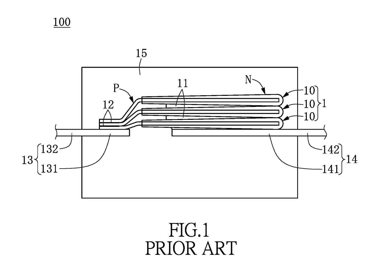
However, during the process of forming the package body 15, an air-tight package may not be achieved or defects or microvoids may form due to the different heat expansion coefficients between the synthetic resin and the materials of the components in the capacitor assembly 1.
Therefore, it would be unable to achieve a solid electrolytic capacitor package structure with good air-tight and water-tight property, and problems such as short circuit or current leakage might occur, thereby reducing the lifetime of the solid electrolytic capacitor package structure.

Method used


Image

  • Solid electrolytic capacitor package structure and method of manufacturing the same
  • Solid electrolytic capacitor package structure and method of manufacturing the same
  • Solid electrolytic capacitor package structure and method of manufacturing the same

Examples


Embodiment Construction

[0017]Reference will now be made in detail to the exemplary embodiments of the instant disclosure, examples of which are illustrated in the accompanying drawings. Wherever possible, the same reference numbers are used in the drawings and the description to refer to the same or like parts.

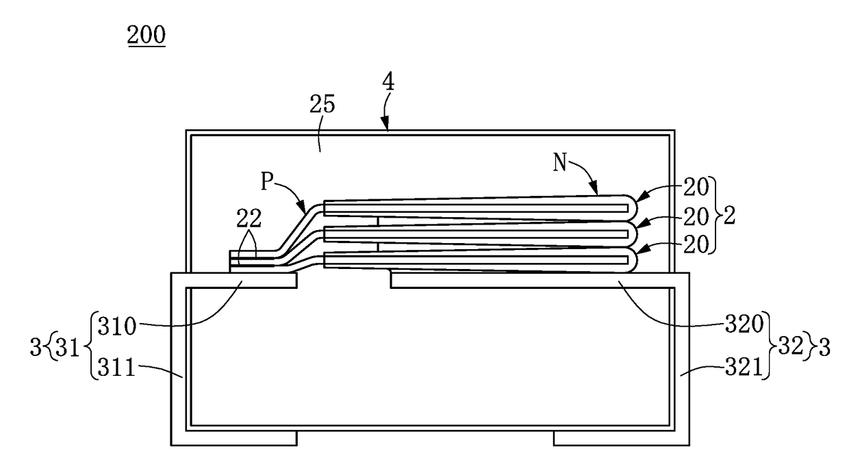
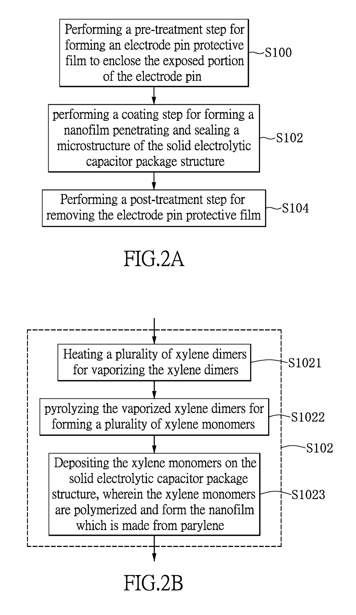
[0018]First, please refer to FIG. 2 to FIG. 4. FIGS. 2A and 2B are the flow charts of the method for manufacturing a solid electrolytic capacitor package structure of the embodiment of the instant disclosure. FIG. 3A to 3C are the schematic views of the solid electrolytic capacitor package structure under different stages during the method for manufacturing a solid electrolytic capacitor package structure of the embodiment of the instant disclosure. FIG. 4A is a partial enlargement of part A in FIG. 3A, and FIG. 4B is a partial enlargement of part B in FIG. 3B. As shown in FIG. 3A, the solid electrolytic capacitor package structure 200 comprises a capacitor assembly 2, an electrode pin 3 electricall...


PUM


Abstract

The instant disclosure provides a solid electrolytic capacitor package structure and method of manufacturing the same. The solid electrolytic capacitor package structure includes a capacitor assembly, at least one electrode pin and a package body enclosing the capacitor assembly and the electrode pin. The electrode pin includes an embedded portion enclosed by the package body and an exposed portion positioned outside the package body. The method of manufacturing the solid electrolytic capacitor package structure includes a protection step including forming a protecting film on the exposed portion; a coating step including depositing a nanomaterial on the solid electrolytic capacitor package structure to form a nanofilm, wherein the nanomaterial penetrates into defects of the solid electrolytic capacitor package structure; and a deprotection step including removing the protecting film. The instant disclosure provides improved air-tight and water-tight properties of the solid electrolytic capacitor package structure, thereby increasing the lifetime thereof.

Description

BACKGROUND[0001]1. Technical Field[0002]The instant disclosure relates to a solid electrolytic capacitor package structure and method of manufacturing the same, in particular, to a solid electrolytic capacitor package structure for electronic products and method of manufacturing the same.[0003]2. Description of Related Art[0004]Capacitors are widely used as basic components of consumer home appliances, computer motherboards, power supplies, communication products and vehicles, etc. The main function of the capacitors include filtering, bypassing, rectifying, coupling, decoupling and phase inversing, etc., and the capacitors are essential in the electronic products. According to different materials and applications, capacitors may be characterized into various types such as aluminum electrolytic capacitors, tantalum electrolytic capacitors, multi-layer ceramic capacitors and thin film capacitors.[0005]The existing solid electrolytic capacitor has the advantages of small size, large c...

Claims


Application Information

Patent Timeline
Patent Type & Authority Applications(United States)
IPC IPC(8): H01G9/10H01G9/26H01G13/00H01G9/15
CPCH01G9/10H01G13/003H01G9/26H01G9/15H01G9/012H01G9/14
Inventor LIN, CHING-FENGKAO, LIANG-MINHUANG, CHUN-CHIA
Owner APAQ TECH
Learn More