Echogenic needle assemblies and method of use thereof

a technology of echogenic needles and needle parts, applied in the field of echogenic needle assemblies, can solve the problems of not being very visible under ultrasound, and achieve the effect of improving the ultrasound image of the echogenic needl

Pending Publication Date: 2017-04-27
SMITHS MEDICAL INT
View PDF16 Cites 8 Cited by
  • Summary
  • Abstract
  • Description
  • Claims
  • Application Information

AI Technical Summary

Benefits of technology

[0005]A first embodiment of an echogenic needle of the instant invention has at its distal portion adjacent its patient end at least one section that has a spiral V-shaped groove. The walls of the groove are orthogonal to each other. The groove is tilted at a given angle from its neutral position toward the proximal end of the needle. The embodiment needle is usually inserted into a subject patient at a desirable insertion angle. If the needle is under ultrasound imaging whereby an ultrasound wave is directed to the needle, at least one wall of the tilted groove would reflect the ultrasound wave back to the receiver of the transducer at substantially the reverse direction, i.e., at approximately 180°, to present an improved ultrasound image of the echogenic needle.

Problems solved by technology

Some of these devices are not normally very visible under ultrasound because of their shape, size or the fact that the material from which they are made has similar reflectance acoustic impedance to the tissue or body fluid within which they are inserted.

Method used


Image

  • Echogenic needle assemblies and method of use thereof
  • Echogenic needle assemblies and method of use thereof
  • Echogenic needle assemblies and method of use thereof

Examples


Embodiment Construction

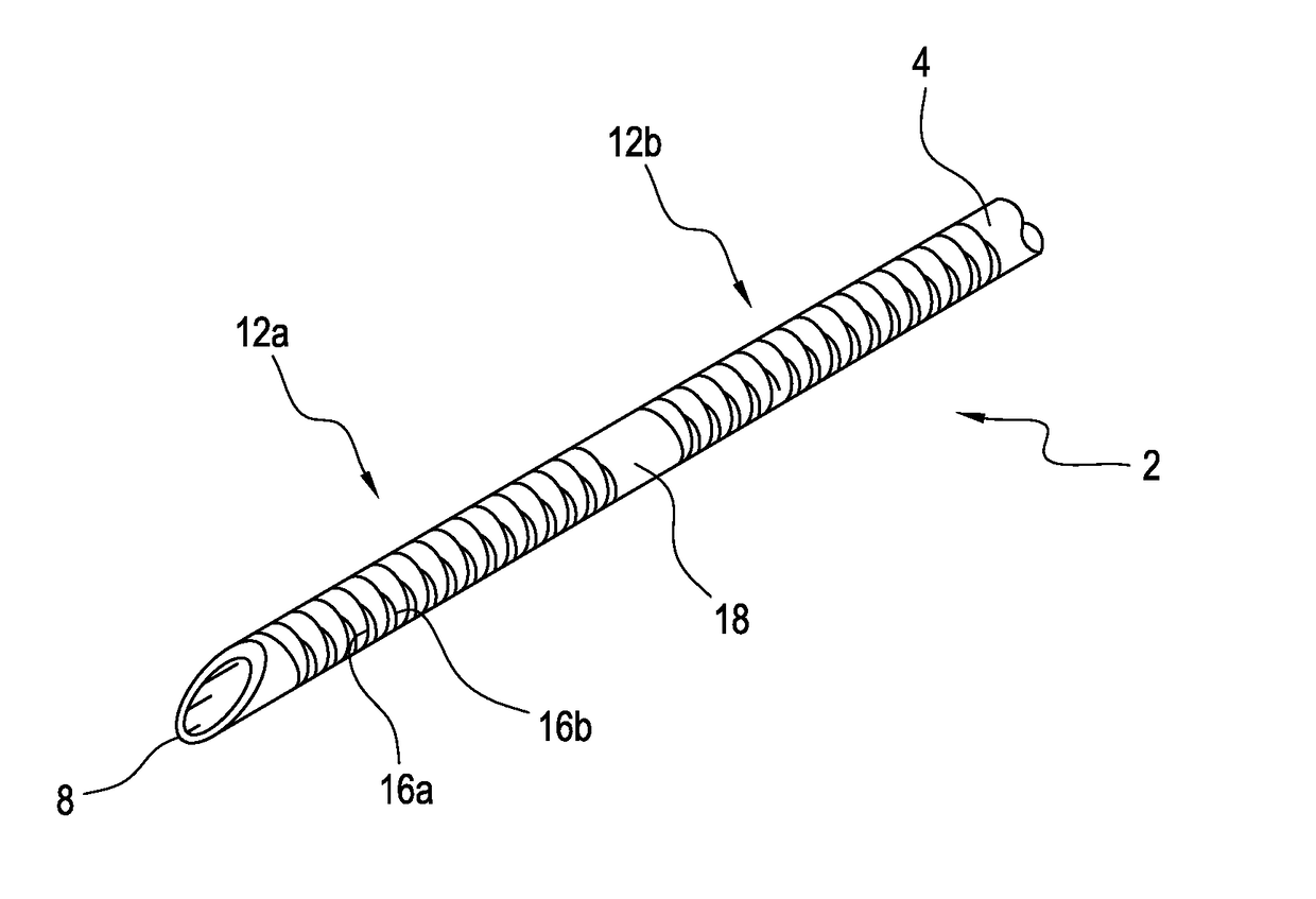
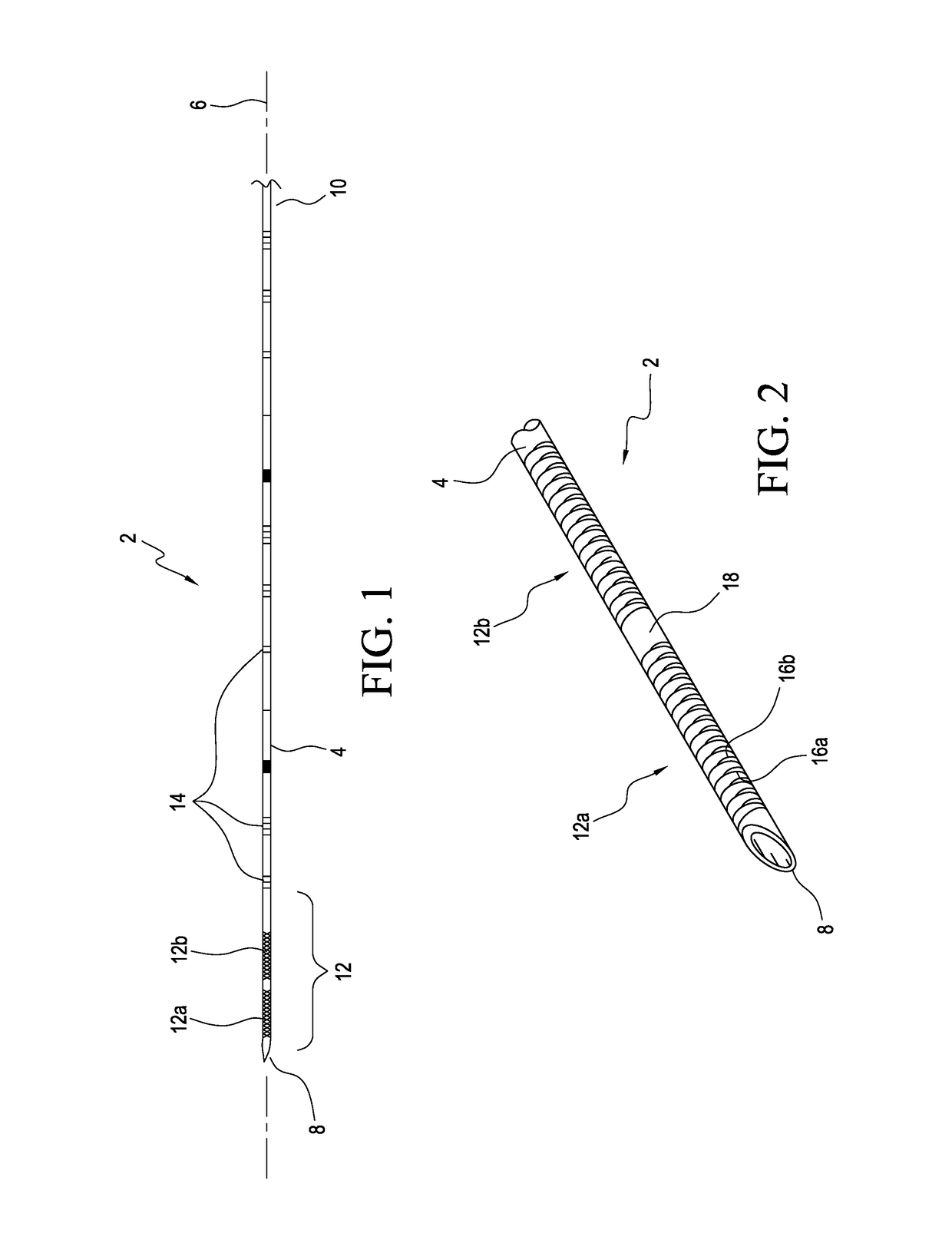
[0031]An exemplar embodiment of the needle used, for example for peripheral nerve block procedures, is shown in FIG. 1. As shown, needle 2 has a shaft 4 that extends along a longitudinal axis 6 having a distal or patient end 8 including a sharp bevel tip and a proximal end 10. For ease of illustration, the proximal end 10 of needle 2 has been truncated in FIG. 1. The section of the needle that is adjacent to patient end 8 is designated distal portion 12, although it should be appreciated that the demarcation of distal portion 12 as shown in FIG. 1 is for discussion only. Beyond distal portion 12 there are a number of markings 14 along the shaft of the needle to show the length, or the depth of the needle, as the needle is inserted into the subject, or patient. There are two sections 12a and 12b at the distal portion that are better illustrated in the enlarged distal portion view of the needle in FIG. 2.

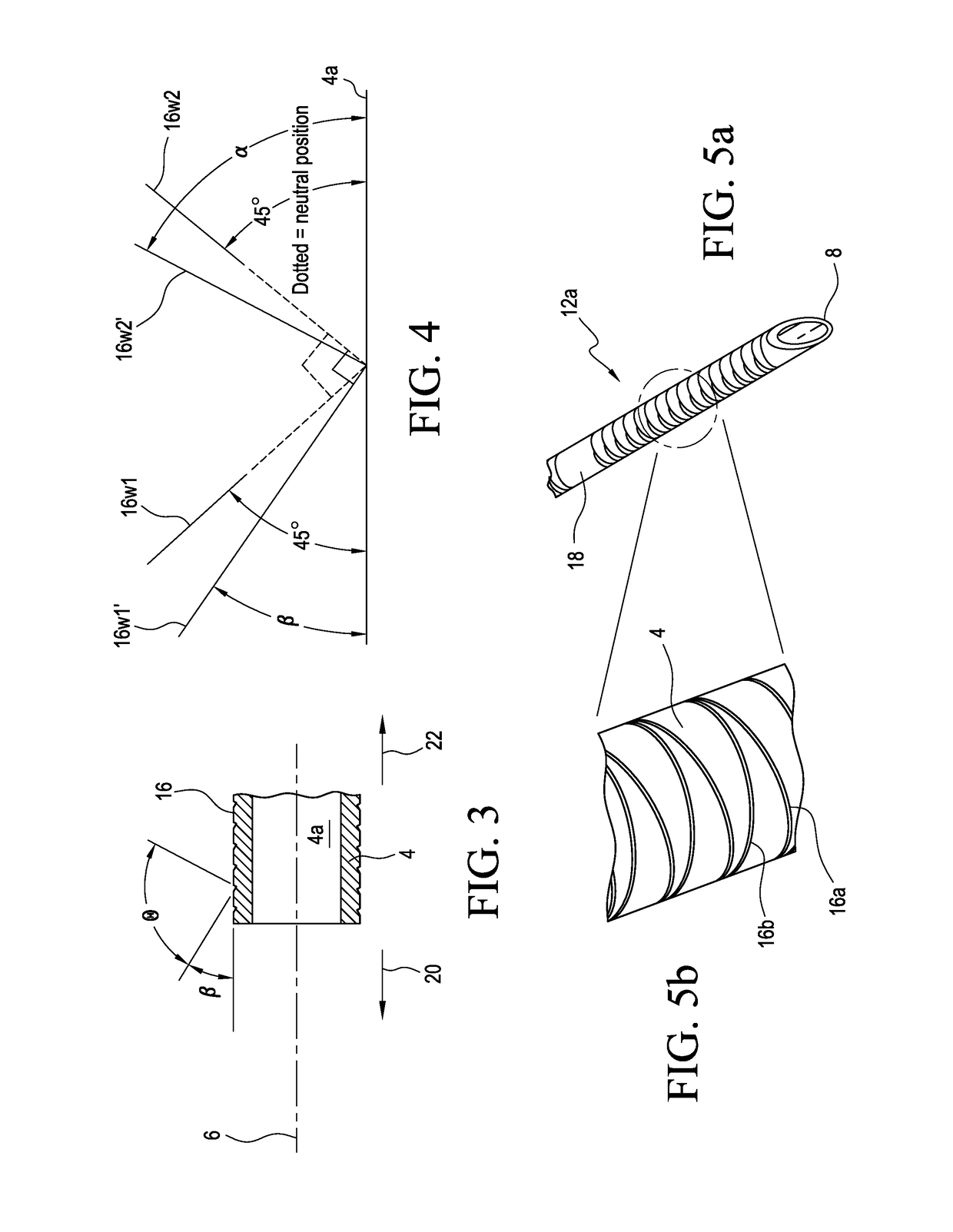
[0032]As shown in FIG. 2, sections 12a and 12b each are formed with crisscrossing...


PUM


Abstract

A needle assembly has a needle having an echogenic feature proximate to its distal sharp tip mounted to an echogenic cannula, with the echogenic tip of the needle extending beyond the distal end of the cannula. The echogenic tip provides guidance for the movement of the needle assembly under ultrasound observation so that the needle assembly may be more readily maneuvered inside a body. Once correctly positioned, the needle is removed and further confirmation may be made under ultrasound observation that the cannula has been correctly positioned inside the body. The echogenic feature of the needle may be at least one spiral groove that is tilted at an angle relative to the tip of the needle to effect a substantially 180° reflection of the ultrasound. An alternative echogenic feature to improve reflected echogeneity has crisscrossing grooves each having a predetermined pitch density formed at a neutral position on the needle.

Description

FIELD OF THE INVENTION[0001]The present invention relates to echogenic medical devices, and more particularly an echogenic needle assembly that may be used to more accurately place and position a cannula into a body.BACKGROUND OF THE INVENTION[0002]Ultrasound scanners are used increasingly to help direct or check placement of catheters and other devices inserted in the body. Some of these devices are not normally very visible under ultrasound because of their shape, size or the fact that the material from which they are made has similar reflectance acoustic impedance to the tissue or body fluid within which they are inserted. Attempts have been made to increase the visibility of medico-surgical devices under ultrasound observation in various ways. Where the device, such as a needle, is of a metal, the usual way of increasing its visibility is by modifying its surface, such as by forming grooves or indentations in its surface. One such echogenic needle known is the Wallace Amniocente...

Claims


Application Information

Patent Timeline
Patent Type & Authority Applications(United States)
IPC IPC(8): A61B17/34A61B8/00A61B8/08
CPCA61B17/3403A61B8/0841A61B2017/3413A61B17/3415A61B17/3423A61B8/4483A61B2090/3925A61B17/3417A61B90/39
Inventor CRISMAN, ANDREWFIELD, STEPHEN JAMESGRANATA, ALYSA LAURENTOOKMAN, NEIL ADAM
Owner SMITHS MEDICAL INT
Why Eureka
Try Eureka