Strip or lap comprising loops, in the form of a laminate with printed patterns

Active Publication Date: 2017-04-27
APLIX INC
View PDF12 Cites 0 Cited by
  • Summary
  • Abstract
  • Description
  • Claims
  • Application Information

AI Technical Summary

Benefits of technology

[0010]The object of the invention is to overcome the disadvantages of the prior art by proposing a laminate forming a strip or lap comprising loops of a self-fastening hook and loop system, in particular for a diaper, which, whil

Problems solved by technology

Moreover, it results in the new possibility of using during this securing process a welding step, whereas in the prior art this type of process was impossible due

Method used


Image

  • Strip or lap comprising loops, in the form of a laminate with printed patterns
  • Strip or lap comprising loops, in the form of a laminate with printed patterns
  • Strip or lap comprising loops, in the form of a laminate with printed patterns

Examples


example

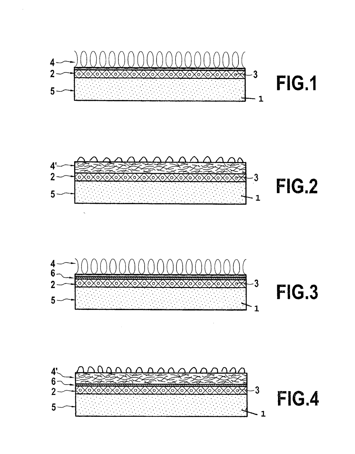
[0088]As a supporting non-woven fabric one takes an SMS with a surface density equal to 13 g / m2, of which the filaments of the layers of Spunbound have an average diameter equal to 15 micrometers and the filaments of the layer of Meltblown have an average diameter of 6 micrometers, whereas the ink is made up of a mixture of a nitrocellulose resin (1%), polyacetate (12%), ethanol (47%) and pigments (5%).

[0089]The adhesive tape test is then applied and finds a printed surface ratio of 1.54%.

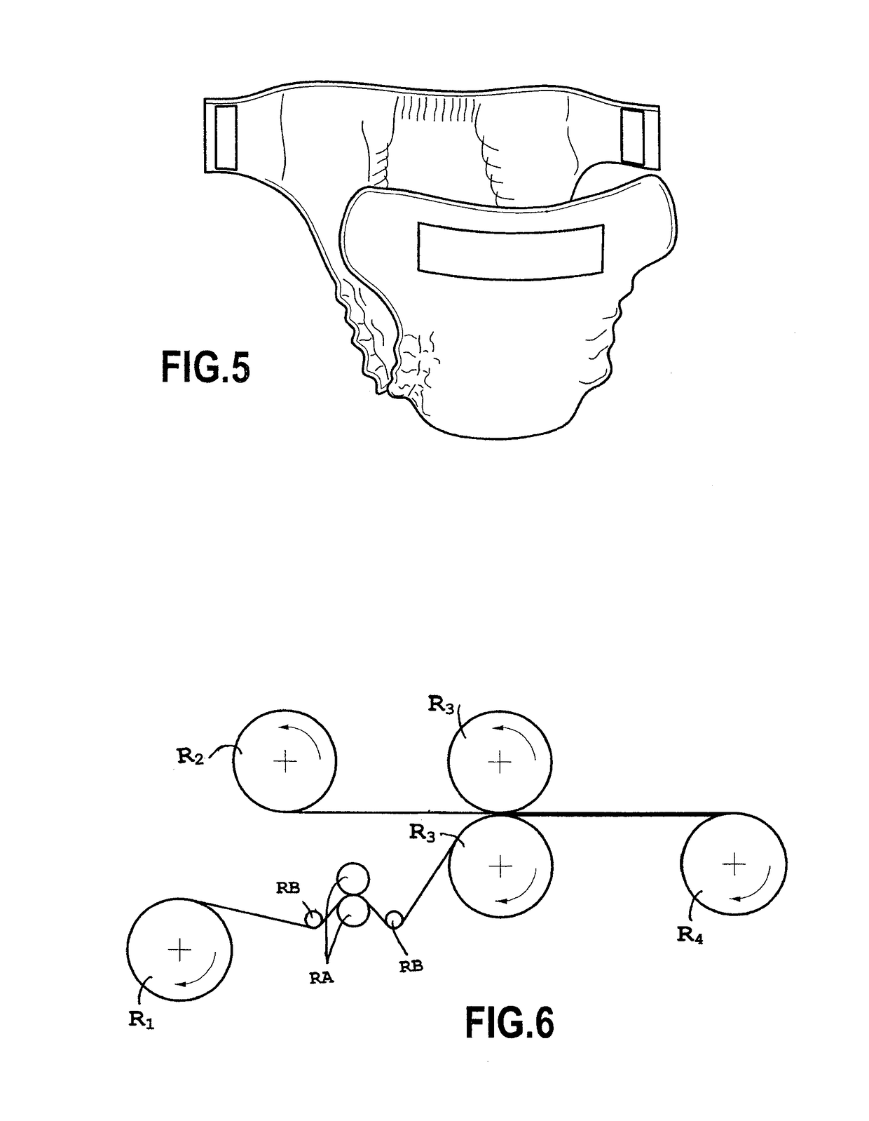
[0090]FIG. 6 shows a basic diagram of an installation for the production of a laminate according to FIG. 2.

[0091]This installation shows in sequence both the printing of the SMS and the calendering of the calendered carded part on the printed SMS. In one embodiment one could envisage separating the two production steps.

[0092]According to the example shown in FIG. 6, the roll R1 is arranged so as to unroll the unprinted SMS so that it is printed by the rolls RB, the function of the rolls RA being to...


PUM

PropertyMeasurementUnit
Speedaaaaaaaaaa
Thicknessaaaaaaaaaa
Permeabilityaaaaaaaaaa

Abstract

The invention relates to a strip or lap comprising loops, in the form of a laminate with printed patterns. The laminate for forming a loop strip or lap, in particular the landing zone of nappies, includes at least one nonwoven layer having a lower face and an upper face opposite the lower face; at least one layer of ink applied to the upper face of at least the nonwoven layer; and at least one external textile layer from which loops project externally in order to engage with hooks of a self-fastening hook and loop device, at least one textile layer being secured to the upper face of at least the nonwoven layer.

Description

TECHNICAL DOMAIN[0001]The present invention relates to a strip or lap comprising loops, in the form of a laminate, for forming the loop part of a self-fastening hook and loop device, in particular for diapers and in particular for forming a band disposed in the front part of the diaper in a central position on the belt, the band classically called the “landing zone”, to enable closure of the belt of the diaper by means of the attachment with hooks emanating from legs disposed in parts of lateral ends of the rear part of the diaper. The present invention also relates to an element comprising at least one non-woven layer on an external face of which at least one layer of ink has been applied, a textile layer with loops being intended to be secured on said external face of the at least one non-woven layer.BACKGROUND TO THE INVENTION[0002]Already known from the prior art are strips or laps of this type in the form of a laminate comprising a non-woven textile layer forming a support on a...

Claims


Application Information

Patent Timeline
IPC IPC(8): A61F13/62B32B7/12B32B5/02B32B5/26A44B18/00A61F13/514
CPCA61F13/627A44B18/0011A44B18/0069A61F13/51496A61F13/51405B32B5/022B32B2555/02B32B5/26B32B7/12A61F2013/8497B32B2250/03B32B2307/4026B32B5/026A61F13/84B32B5/145B32B2250/04B32B7/08
Inventor MOINARD, NATHALIEMARCHE, THIERRY
Owner APLIX INC
Why Eureka
Try Eureka