
Gas-filled cushioning device

Inactive Publication Date: 2010-12-14
BASF COATINGS GMBH
View PDF101 Cites 19 Cited by
  • Summary
  • Abstract
  • Description
  • Claims
  • Application Information

AI Technical Summary

Benefits of technology

[0031]To achieve the foregoing objects, the present invention provides barrier membranes which have (1) a desirable level of flexibility (or rigidity); (2) a desirable level of resistance to degradation caused by moisture; (3) an acceptable level of imperviousness to fluids which can be in the form of gases, liquids or both depending mainly on the intended use of the product; and (4) are highly resistant to delamination when employed in a multi-layer structure. Regardless of the barrier membrane embodiment, each barrier membrane in accordance with the teachings of the present invention includes a barrier layer comprised at least in part of a blend of at least one aliphatic thermoplastic urethane and at least one copolymer of ethylene and vinyl alcohol.
[0038]Ideally, the flexible barrier materials utilized in accordance with the teachings of the present invention should be capable of containing a captive gas for a relatively long period of time. In a highly preferred embodiment, for example, the barrier membrane should not lose more than about 20% of the initial inflated gas pressure over a period of two years. In other words, products inflated initially to a steady state pressure of between 20.0 to 22.0 psi should retain pressure in the range of about 16.0 to 18.0 psi.
[0040]As alluded to above, a significant feature of the barrier membranes of the present invention is the ability under embodiments formed into products intended to be inflated (such as cushioning devices for footwear) to control diffusion of mobile gases through the membrane and to retain the captive gases contained therein. By the present invention, not only are super gases usable as captive gases, but nitrogen gas may also be used as a captive gas due to the performance of the barrier. The practical effect of providing a barrier membrane for which nitrogen gas is a captive gas is significant in terms of protection of the earth's ozone and global warming.
[0041]Under the present invention, if the barrier membrane is formed into a product such as a cushioning device, the membrane may be initially inflated with nitrogen gas or a mixture of nitrogen gas and one or more super gases or with air. If filled with nitrogen or a mixture of nitrogen and one or more super gases, an increment of pressure increase results from the relatively rapid diffusion of oxygen gas into the membrane, since the captive gas is essentially retained within the membrane. This effectively amounts to an increase in pressure of not greater than about 2.5 psi over the initial inflation pressure and results in a relatively modest volume growth of the membrane of between 1 to 5%, depending on the initial pressure. However, if air is used as the inflatant gas, oxygen tends to diffuse out of the membrane while the nitrogen is retained as the captive gas. In this instance, the diffusion of oxygen out of the membrane and the retention of the captive gas results in an incremental decrease of the steady state pressure over the initial inflation pressure.
[0042]A further feature of the present invention is the enhanced bonding which occurs between contiguous layers, thus, eliminating the need for adhesive tie layers. This is generally accomplished by laminating the first and second layers together using conventional techniques and thus, the laminated barrier membranes of the present invention are characterized in that significant hydrogen bonding occurs between a first layer formed from a blend of at least one aliphatic thermoplastic urethane and a copolymer of ethylene and vinyl alcohol, and a second layer of thermoplastic urethane. In addition to the occurrence of hydrogen bonding, it is theorized that there will also generally be a certain amount of covalent bonding between the first and second layers, especially when lesser amounts of the copolymer of ethylene and vinyl alcohol is used in the first layer and the thermoplastic urethanes of both the first and second layers have similar functionalities.

Problems solved by technology

Often, however, materials which exhibit acceptable flexibility characteristics tend to have an unacceptably low level of resistance to gas permeation.
In contrast, materials which exhibit an acceptable level of resistance to gas permeation tend to have an unacceptably low level of flexibility.
While Moreaux '110 attempts to address the concerns in the art relating to flexibility and imperviousness to gases, a perceived drawback of Moreaux is that the film described is not processable utilizing conventional sheet extrusion techniques.
The gradual increase in bladder pressure typically causes an increase in tension in the bladder skin, resulting in a volume increase due to stretching.
With regard to the systems utilized within the shoe manufacturing industry prior to and shortly after the introduction of the Air Sole™ athletic shoes, many of the midsole bladders consisted of a single layer gas barrier type films made from polyvinylidene chloride based materials such as Saran® (which is a registered trademark of the Dow Chemical Co.) and which by their nature are rigid plastics, having relatively poor flex fatigue, heat sealability and elasticity.
Still further, bladder films made under techniques such as laminations and coatings which involve one or more barrier materials in combination with a flexible bladder material (such as various thermoplastics) can potentially present a wide variety of problems to solve.
Such difficulties with composite constructions include layer separation, peeling, gas diffusion or capillary action at weld interfaces, low elongation which leads to wrinkling of the inflated product, cloudy appearing finished bladders, reduced puncture resistance and tear strength, resistance to formation via blow-molding and / or heat-sealing and R-F welding, high cost processing, and difficulty with foam encapsulation and adhesive bonding, among others.
Yet another issue with previously known bladders is the use of tie-layers or adhesives in preparing laminates.
The use of such tie layers or adhesives generally prevent regrinding and recycling of any waste materials created during product formation back into an usable product, and thus, also contribute to high cost of manufacturing and relative waste.
In this regard, the principal concern was the lack of fatigue resistance of the barrier layer.
Under such a construction, relatively complicated and expensive processing controls such as strict time-temperature relationships and the use of heated platens and pressures, coupled with a cold press to freeze the materials together under pressure would be required.
Additionally, using adhesive tie layers or incorporating crystalline components into the flexible film at high enough levels to accomplish a gas transmission rate of 10.0 or less, reduces the flexibility of the film.

Method used


Image

  • Gas-filled cushioning device
  • Gas-filled cushioning device
  • Gas-filled cushioning device

Examples


Embodiment Construction

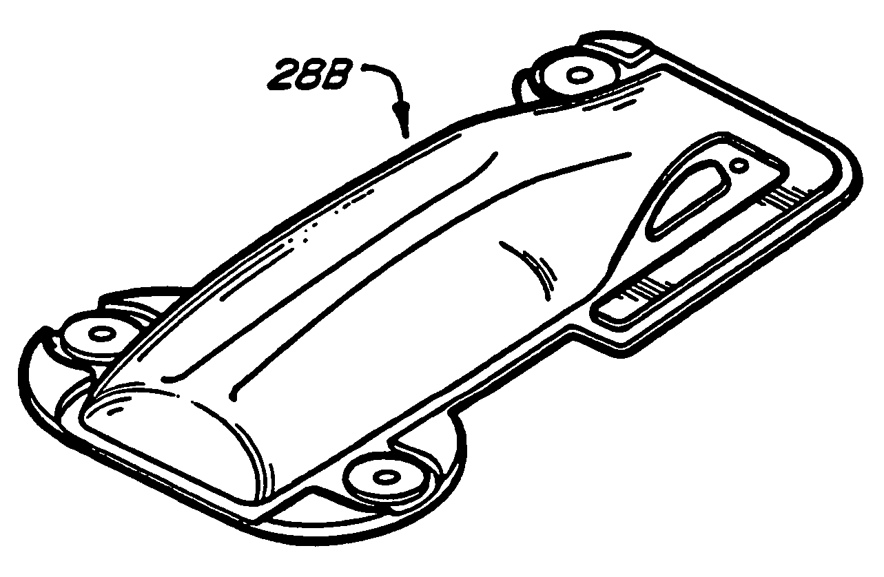
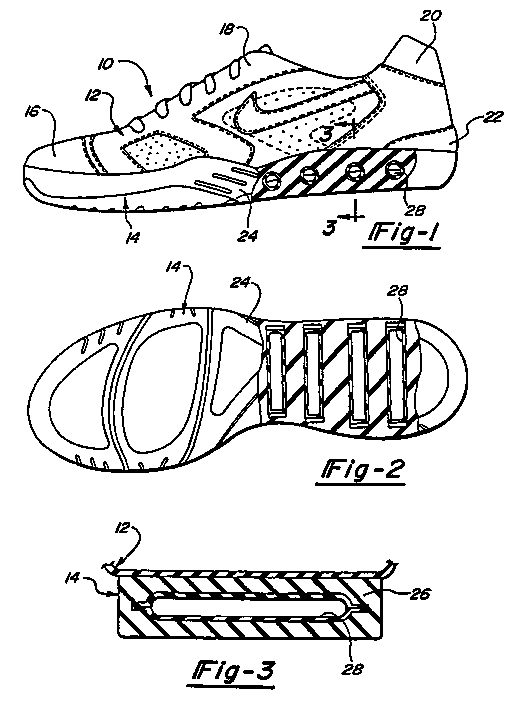
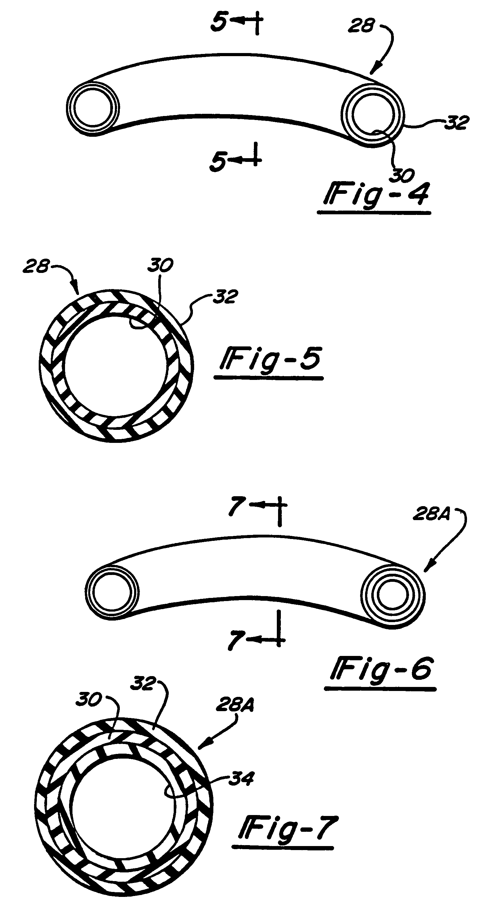
[0067]Referring to FIGS. 1-5, there is shown an athletic shoe, including a sole structure and a cushioning device as one example of a product employing a barrier membrane in accordance with the teachings of the present invention. The shoe 10 includes a shoe upper 12 to which the sole 14 is attached. The shoe upper 12 can be formed from a variety of conventional materials including, but not limited to, leathers, vinyls, nylons and other generally woven fibrous materials. Typically, the shoe upper 12 includes reinforcements located around the toe 16, the lacing eyelets 18, the top of the shoe 20 and along the heel area 22. As with most athletic shoes, the sole 14 extends generally the entire length of the shoe 10 from the toe region 20 through the arch region 24 and back to the heel portion 22.

[0068]The sole structure 14 includes one or more selectively permeable barrier membranes 28 in accordance with the present invention, which are preferably disposed in the midsole H of the sole s...


PUM

PropertyMeasurementUnit
Thicknessaaaaaaaaaa
Thicknessaaaaaaaaaa
Thicknessaaaaaaaaaa

Abstract

A shoe is fabricated from an upper structure and a sole structure wherein the sole structure contains a gas-filled cushioning device composed of a multi-layer film formed into a gas-filled membrane having an interior compartment enclosing at least one capture gas. The multi-layer film comprises an outer layer of an elastomeric thermoplastic material such as a polyurethane, an inner layer of an elastomeric thermoplastic material such as a polyurethane and a barrier layer interposed therebetween which is derived from a combination of at least one ethylene-vinyl alcohol copolymer and up to about 50 wt. % of an aliphatic thermoplastic urethane.

Description

CROSS-REFERENCE TO RELATED APPLICATIONS[0001]This application is a division of application Ser. No. 10 / 377,540, filed Feb. 28, 2003 now U.S. Pat. No. 6,730,379, which is a division of application Ser. No. 09 / 170,790, filed Oct. 13, 1998 (U.S. Pat. No. 6,599,597), which is a continuation of application Ser. No. 08 / 475,276, filed Jun. 7, 1995, now abandoned.FIELD OF THE INVENTION[0002]The present invention relates to barrier membranes and, more particularly, to barrier membranes which, under certain embodiments, serve to selectively control the diffusion of gases through the membrane. Additionally, under certain embodiments, the membrane not only selectively controls the diffusion of gases through the membrane, but also allows for the controlled diffusion of gases normally contained in the atmosphere.[0003]For a further understanding of the scope of the present invention, reference can be made to U.S. patent application Ser. No. 08 / 299,287 entitled “Cushioning Device With Improved Fle...

Claims


Application Information

Patent Timeline
IPC IPC(8): B32B27/08B32B1/08B29C48/10B29C49/00B29C49/04B29C49/22B32B27/40
CPCB29C47/0021B29C47/065B29C47/145B29C49/0005B32B27/08B32B27/40Y10T428/1386B29C47/0059B29C49/04B29C49/22B29L2031/504B29L2031/52Y10T428/1379Y10T428/1352Y10T428/13Y10T428/1393Y10T428/1383B29C47/0054B29C48/08B29C48/0017B29C48/0019B29C48/21B29C48/307Y10T428/31551Y10T428/31554B29C48/10B32B27/306B32B2375/00B32B2437/02
Inventor BONK, HENRY WGOLDWASSER, DAVID
Owner BASF COATINGS GMBH
Learn More