Reflective polarizer, laminated optical member, and liquid crystal display apparatus

Inactive Publication Date: 2007-04-26
SUMITOMO CHEM CO LTD
View PDF3 Cites 4 Cited by
  • Summary
  • Abstract
  • Description
  • Claims
  • Application Information

AI Technical Summary

Benefits of technology

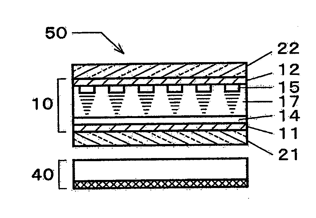
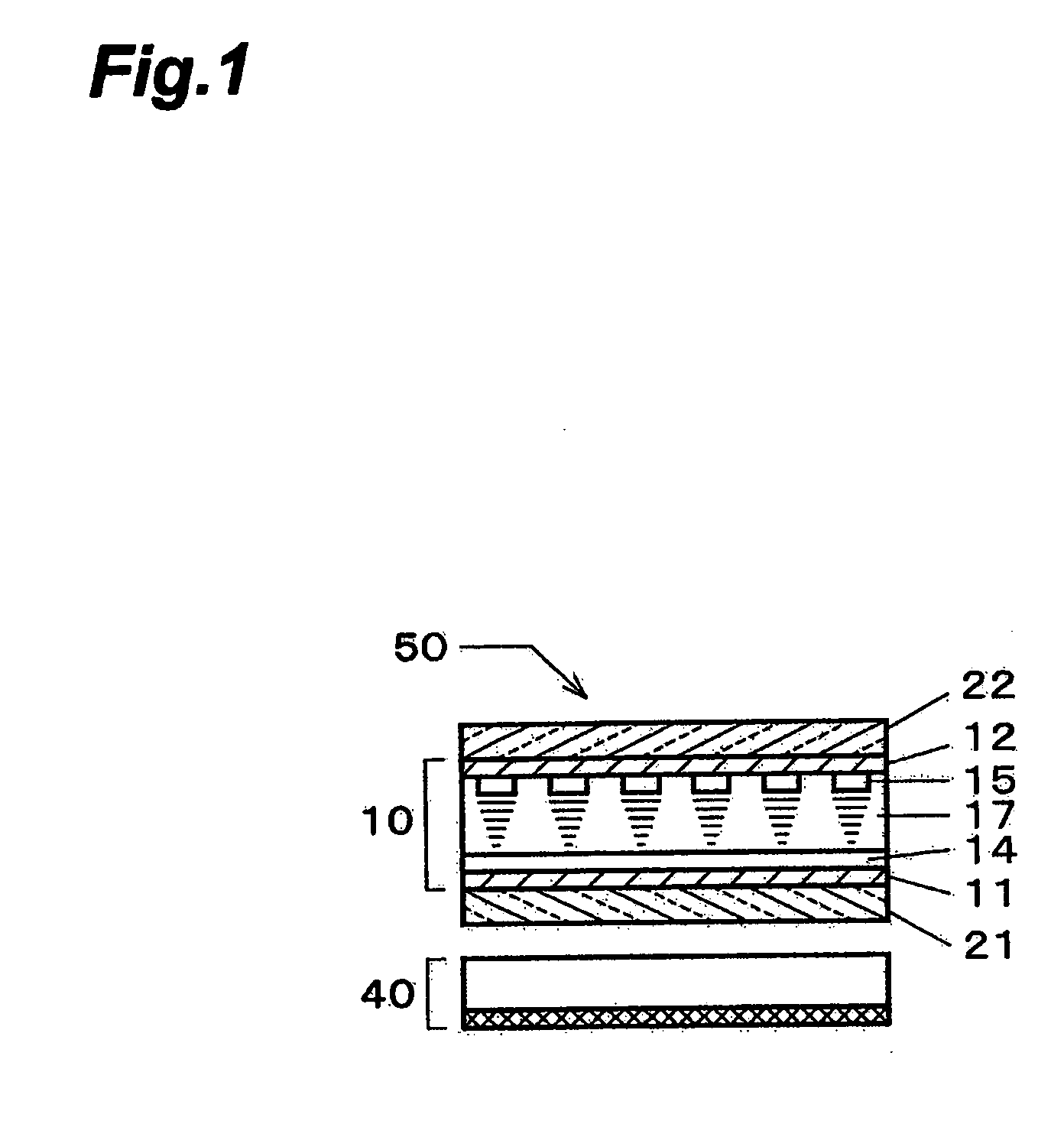
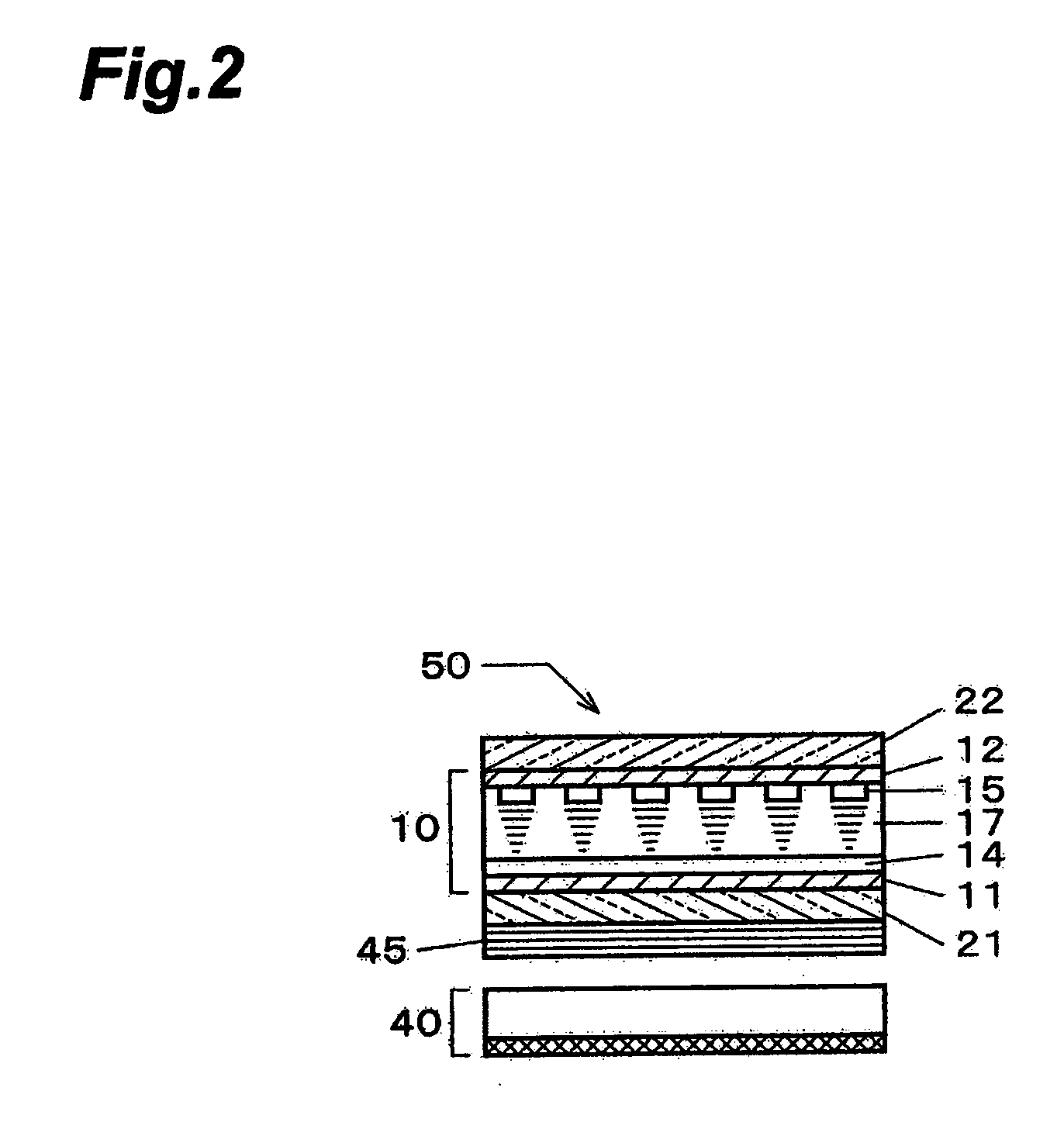
[0025] The reflective polarizer of the present invention has a structure in which the birefringent bodies are dispersed and oriented substantially in one direction, by the simple method, and is resistant to delamination because the interface between different materials is not a simple plane. Since the support medium for supporting the birefringent bodies is made of the isotropic substance, the reduction of its strength is relatively small with increase in the volume fraction of the birefringent bodies, and it is thus easy to increase the volume fraction of the birefringent bodies. Furthermore, by locating this reflective polarizer on the opposite side to an observer of the liquid crystal panel with the absorptive polarizer, it becomes feasible to provide the liquid crystal display apparatus capable of achieving high luminance and low power consumption because the efficiency of utilization of light is increased.

Problems solved by technology

It is, however, difficult for this reflective polarizer to convert the right-handed (or left-handed) circularly polarized light from the cholesteric liquid crystal layer into linearly polarized light by the quarter wave plate of a single layer over the wavelength range of visible light.
Production steps for forming a stack of quarter wave plates become complicated and there will arise a problem that delamination of the quarter wave plates can occur.
The lamination of different materials can also pose a problem that delamination of the layers is likely to occur.
However, if the continuous medium is made of a uniaxially oriented substance demonstrating significant birefringence, increase in a volume fraction of the dispersed phases may result in failure in maintaining its film shape because of a reduction of its strength.
For this reason, the volume fraction of the dispersed phases needs to be kept low, and it will pose a problem that it is difficult to enhance the polarization split efficiency.

Method used


Image

  • Reflective polarizer, laminated optical member, and liquid crystal display apparatus
  • Reflective polarizer, laminated optical member, and liquid crystal display apparatus
  • Reflective polarizer, laminated optical member, and liquid crystal display apparatus

Examples


example 1

[0109] This example shows optical characteristics in the case where six triangular prisms with the sectional shape of a regular triangle are in contact with each other at the apexes of the respective sectional regular triangles to form a regular hexagonal prism, i.e., where triangular prisms are uniformly dispersed in the support medium in the form of the Star of David. The orthogonal coordinate system of the right hand system to express positions in the simulation space is defined as (x,y,z) and the schematic view of the system used in the calculation in this example is presented in FIG. 12. In FIG. 12, part (a) schematically shows a rectangular parallelepiped region used in the calculation, on the right-hand (x,y,z) orthogonal coordinate system, part (b) is a schematic sectional view, taken along the y-z plane at x=0, of this rectangular parallelepiped, and part (c) shows the direction of the coordinate system in part (b). It is noted that in these drawings, particularly, in part ...

example 2

[0121] This example shows optical characteristics in the case where the triangular prisms are uniformly dispersed in the support medium so that three triangular prisms with the sectional shape of a regular triangle are in contact at respective apexes of sectional regular triangles to form a regular triangular prism. The orthogonal coordinate system of the right hand system to express positions in the space is defined by (x,y,z) and the schematic view of the system used in the calculation in this example is presented in FIG. 13. In FIG. 13 part (a) schematically shows a rectangular parallelepiped region used in the calculation in the right-hand (x,y,z) orthogonal coordinate system, part (b) is a schematic sectional view of this rectangular parallelepiped on the y-z plane at x=0, and part (c) shows the directions of the coordinate axes in part (b). It is noted that in these drawings, particularly, in part (a), the scale size does not correspond to the original size. The unit of numera...

example 3

[0130] This example shows optical characteristics in the case where triangular prisms are uniformly dispersed in the support medium so that three triangular prisms having the sectional shape of an isosceles triangle are in contact with apexes of bottoms of the other isosceles triangles at an apex of an apex angle in each sectional isosceles triangle so as to form an isosceles triangular prism. The orthogonal coordinate system of the right hand system to express positions in the region is defined by (x,y,z) and the schematic view of the system used in the calculation in this example is presented in FIG. 14. In FIG. 14 part (a) schematically shows a rectangular parallelepiped region used in the calculation on the right-hand (x,y,z) orthogonal coordinate system, part (b) is a schematic sectional view of this rectangular parallelepiped on the y-z plane at x=0, and part (c) shows the directions of the coordinate axes in part (b). It is noted that in these drawings, particularly, in part ...


PUM


Abstract

It is an object to provide an optical member capable of enhancing efficiency of utilization of light in a liquid crystal display apparatus by laminating a reflective polarizer with an optical layer having another optical function, and it is another object to provide a liquid crystal display apparatus with increased efficiency of utilization of light from a backlight, using the laminated optical member with the reflective polarizer. The present invention provides a reflective polarizer comprising birefringent bodies including polygonal prisms or circular cylinders a shape of a cross section of which perpendicular to a long axis direction is polygonal or substantially circular, which has an aspect ratio of not less than 2, and which has a refractive index difference of not less than 0.05 between a refractive index in the long axis direction and a refractive index in a short axis direction. The birefringent bodies are dispersedly arranged substantially in an identical direction in a support medium, and where the shape of the cross section perpendicular to the long axis direction of the birefringent bodies is substantially circular, any one of the birefringent bodies, when viewed on the cross section, is in contact on a side face of a circular cylinder with each of at least two other birefringent bodies in contact on a side face of a circular cylinder with each other.

Description

TECHNICAL FIELD [0001] The present invention relates to a liquid crystal display apparatus used as a display of a personal computer or the like, and to an optical member and reflective polarizer which are suitably applicable to such liquid crystal display apparatus. BACKGROUND ART [0002] A liquid crystal display apparatus generally used at present includes a panel of a structure in which a nematic liquid crystal is provided between two transparent substrates to form a liquid crystal cell and in which polarizers are located on both sides of this cell. This panel is combined with an LSI for driving and a backlight to constitute a liquid crystal display apparatus. FIG. 1 is a schematic sectional view showing an example of the liquid crystal display apparatus. In this example, transparent electrodes 14, 15 are formed on one side of two transparent substrates 11, 12, respectively, the transparent electrodes are arranged to face each other, and a liquid crystal 17 is provided between them...

Claims


Application Information

Patent Timeline
IPC IPC(8): G02B27/28G02B5/30G02F1/13363
CPCG02B5/3008G02F1/133536G03B21/604G02F2001/133638G02F2413/09G02F1/13363G02F1/133638G02F1/133631G02B5/30
Inventor WATANABE, TOSHIYUKITOTANI, KENROHAYASHI, HIDEKIKUBOTA, MASAAKIISHITOBI, MASAMITSUMATSUOKA, YOSHIKI
Owner SUMITOMO CHEM CO LTD
Why Eureka
Try Eureka