Method of regulating the pressure within a first rocket engine propellant tank

a technology of rocket engine and propellant tank, which is applied in the direction of engine control, cosmonautic components, cosmonautic parts, etc., can solve the problems of complex known devices for regulating pressure in order to regulate pressure within rocket engine propellant tanks, and achieves simple and reliable methods, less expensive, and more reliable effects

Active Publication Date: 2017-04-27
ARIANEGRP SAS
View PDF0 Cites 17 Cited by
  • Summary
  • Abstract
  • Description
  • Claims
  • Application Information

AI Technical Summary

Benefits of technology

[0012]The inventors have found that by controlling the flow rate of each motor-driven pump independently of the other motor-driven pump, and as a function of parameters that are distinct and not correlated, it is possible to regulate the pressure within the first tank in simple and reliable manner. Naturally, the parameters are parameters that relate to the elements of the regulator device, including the first tank. For example, these parameters may be the propellant flow rate, or the pressure or the temperature at a given point in the regulator device, including in the first tank.
[0013]It is thus possible to avoid having the variable-aperture valves of prior art devices for regulating pressure, while conserving only on / off valves for isolating components, where necessary, which valves perform only a safety function and do not perform a regulation function. Such on / off valves are naturally simpler, more reliable, and less expensive than the variable-aperture valves of the prior art.

Problems solved by technology

Known devices for regulating pressure in order to regulate pressure within rocket engine propellant tanks are generally complex both in structure and to use, and in particular they involve the presence of a plurality of variable-aperture valves together with means for controlling them.

Method used


Image

  • Method of regulating the pressure within a first rocket engine propellant tank
  • Method of regulating the pressure within a first rocket engine propellant tank
  • Method of regulating the pressure within a first rocket engine propellant tank

Examples


Embodiment Construction

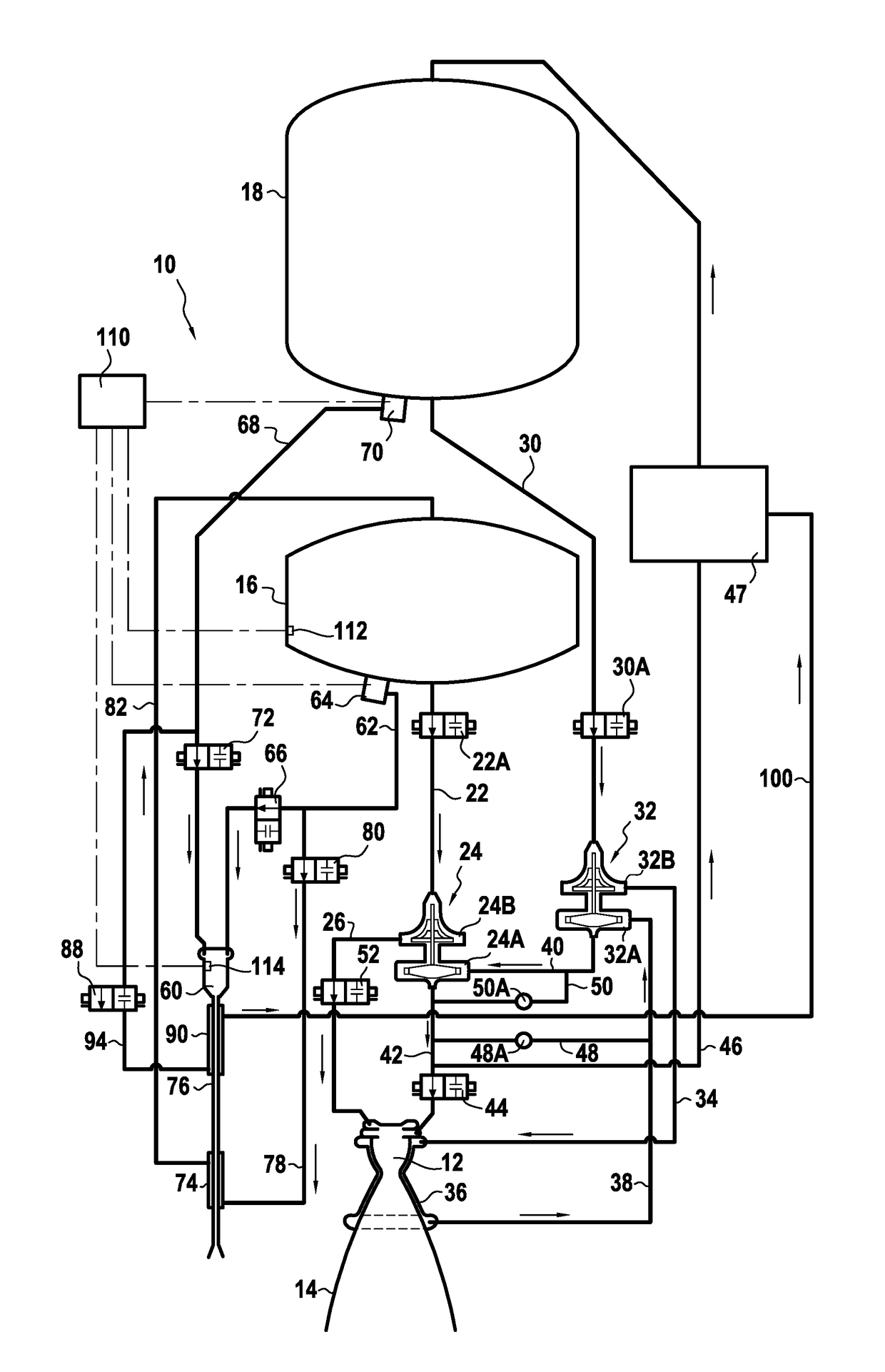
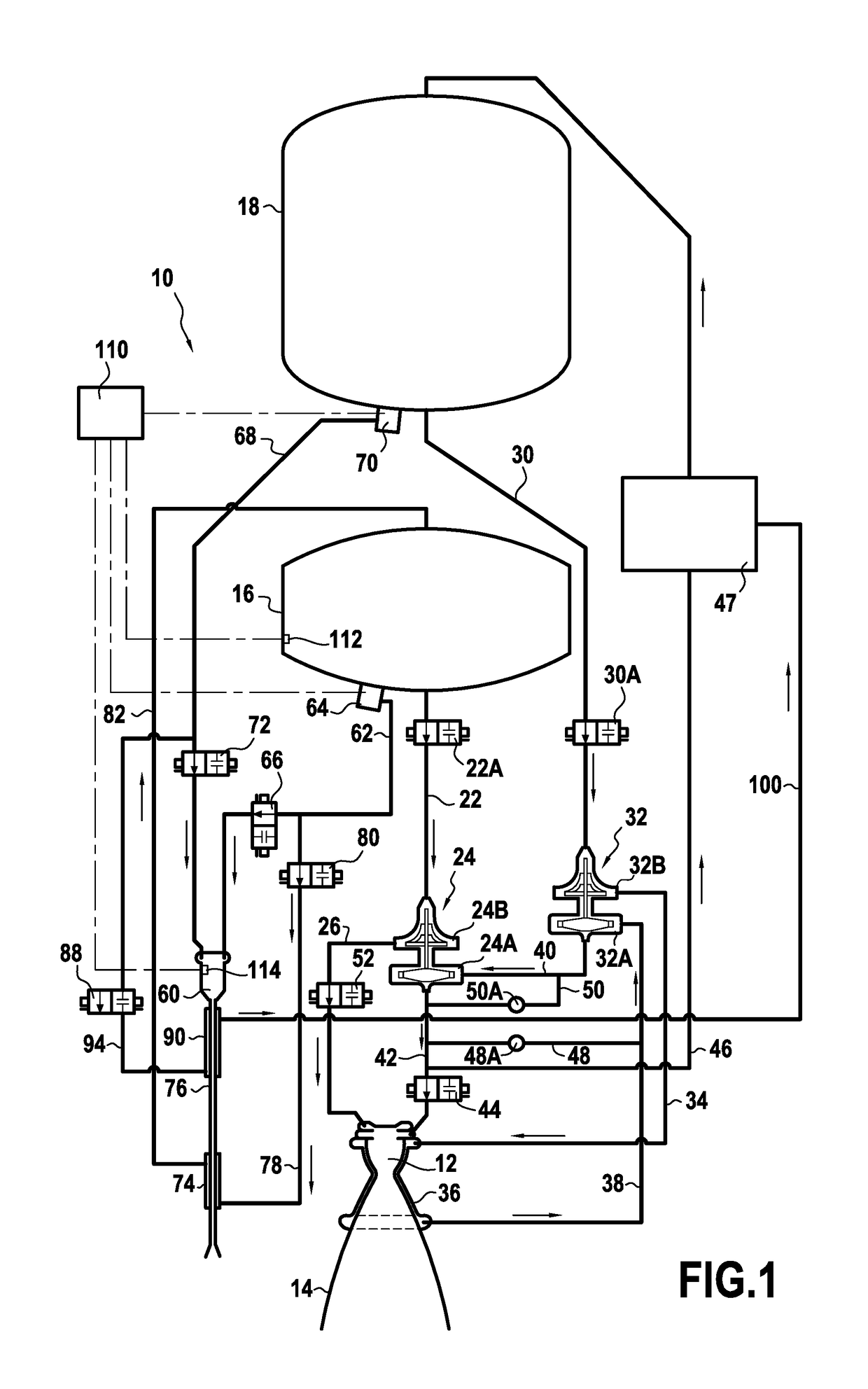
[0037]FIG. 1 shows a rocket engine 10 having a combustion chamber 12 and a nozzle 14 with a diverging portion. The combustion chamber 12 is fed with a first propellant from a first tank 16 containing the first propellant, e.g. an oxidizer propellant such as oxygen, and it is also fed with a second propellant from a second tank 18 containing the second propellant, e.g. a reducing propellant, e.g. hydrogen or methane. The reducing propellant acts as fuel, which enters into combustion with the oxidizer.

[0038]The feed of first propellant from the first tank 16 comprises a main pipe 22 delivering to a first turbopump 24 and a first injection pipe 26 connecting the outlet from the first turbopump 24 to the combustion chamber 12. The feed of second propellant from the second tank 18 comprises a second main feed pipe 30 delivering to a second turbopump 32, and a second injection pipe 34 connected to the outlet of the second turbopump 32.

[0039]Respective authorization valves 22A and 30A are ...


PUM


Abstract

A method of regulating pressure within a first propellant tank of a rocket engine having a first propellant tank containing a first propellant and a second propellant tank containing a second propellant, and a regulator device for regulating pressure within the first tank, the regulator device comprising a gas generator and a heat exchanger co-operating with the gas generator so as to vaporize at least part of the first propellant prior to reintroducing it into the first tank (16), the gas generator and the heat exchanger both being fed with the first propellant by a single first motor-driven pump, while the gas generator is fed with the second propellant by a single second motor-driven pump, wherein the flow rate of the first motor-driven pump is controlled as a function of a first parameter, while the flow rate of the second motor-driven pump is controlled as a function of a second parameter.

Description

CROSS-REFERENCE TO RELATED APPLICATION(S)[0001]This patent application claims the benefit of priority under 35 U.S.C. §119 to French Patent Application No. 1502259, filed on Oct. 26, 2015, the entirety of which is incorporated herein by reference.FIELD OF THE INVENTION[0002]The present invention relates to a method of regulating the pressure within a first rocket engine propellant tank.STATE OF THE PRIOR ART[0003]A rocket engine is conventionally an engine in which the gas leaving the combustion chamber is discharged via a nozzle so as to develop thrust. The gas is generally obtained by combustion between a first propellant and a second propellant. By way of example, the first propellant is an oxidizer, such as oxygen, while the second propellant is a fuel, such as hydrogen or methane.[0004]The propellants are stored in tanks in the liquid state, and the tanks are maintained under pressure in order to ensure that propellants flow to the combustion chamber in regular manner. For this...

Claims


Application Information

Patent Timeline
Patent Type & Authority Applications(United States)
IPC IPC(8): F02K9/56F02K9/42F02K9/46
CPCF02K9/563F05D2270/303F02K9/425F02K9/46F02K9/48F02K9/50F02K9/68F02K9/94F05D2270/301F02K9/42B64G1/402F02K9/44B64G1/401
Inventor HUE, VALENTINLE GONIDEC, SERGE
Owner ARIANEGRP SAS
Why Eureka
Try Eureka