Low-loss few-mode fiber

Active Publication Date: 2017-04-27
FENGHUO COMM SCI & TECH CO LTD +1
View PDF0 Cites 3 Cited by
  • Summary
  • Abstract
  • Description
  • Claims
  • Application Information

AI Technical Summary

Benefits of technology

The present invention provides a low-loss few-mode fiber that reduces transmission loss of optical signals and reduces generation of error codes in communication systems and relay cost. It also effectively filters out undesired polarization mode optical signals and facilitates stable transmission in fiber mode. Additionally, it allows for adjustment of differential group delay in the fiber.

Problems solved by technology

Although the use of increasingly complex algorithms can improve the spectral efficiency, the decrease in bandwidth gains is brought and the modest improvement can not meet the exponentially-growing bandwidth needs, and the spectral efficiency of DWDM in single-mode fibers will approach its theoretical limits.
As germanium-doped quartz has a higher scattering coefficient, a high fiber loss is generated.
Moreover, in an application of ultra-long-distance high-capacity optical fiber communications, the attenuation coefficient of germanium-doped graded-index few-mode fibers at 1550 nm is generally above 0.19 dB, and the attenuation coefficient also varies with the change of ambient temperature conditions, resulting in excessive loss which in turn leads to the increase of error codes in the communication system and the increase of relay costs.
On the other hand, in short-distance transmission (e.g. in fiber jumper applications), linear polarization modes that are undesired for transmission in fibers need to be dissipated rapidly by means of linear polarization modes, or they will bring about difficulties in signal resolution.
Therefore, it becomes a difficult issue for giving consideration to both the low loss in long-distance transmission and the effective attenuation of undesired linear polarization modes in short-distance transmission.

Method used


Image

  • Low-loss few-mode fiber
  • Low-loss few-mode fiber
  • Low-loss few-mode fiber

Examples


Embodiment Construction

[0021]In order to facilitate the understanding of the present invention, the terms used herein are first generally defined as follows:

core layer: a portion located in the center in the view of fiber cross section, acting as the primary light-guiding region of the fiber;

fluorine-doped quartz cladding: an annular region adjacent to the core layer in the view of fiber cross section;

inner cladding: a cladding region adjacent to the fiber core layer; relative refractive index difference:

Δ%=[ni2-n022×ni2]×100%≈ni-n0n0×100%

ni and n0 refer respectively to the refractive indexes of a corresponding portion and its adjacent outside cladding at 1550 nm wavelength;

power exponent law refractive index distribution profile: a refractive index distribution pattern satisfying the following power exponent function, in which n1 refers to the refractive index of the fiber axis; r refers to a distance from the fiber axis; a refers to a radius of the fiber core; α refers to a power exponent of distributio...


PUM


Abstract

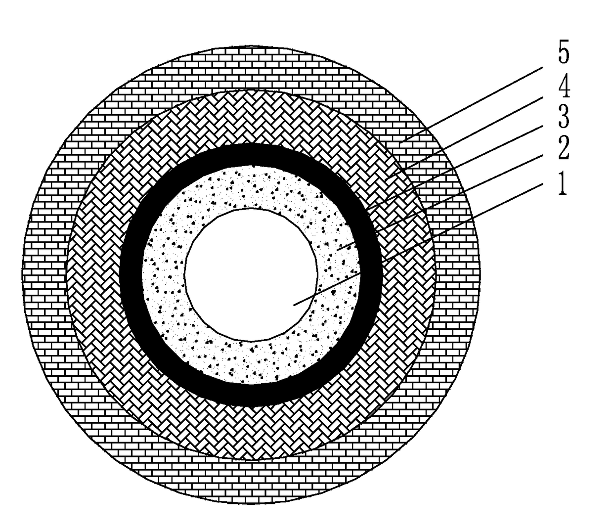
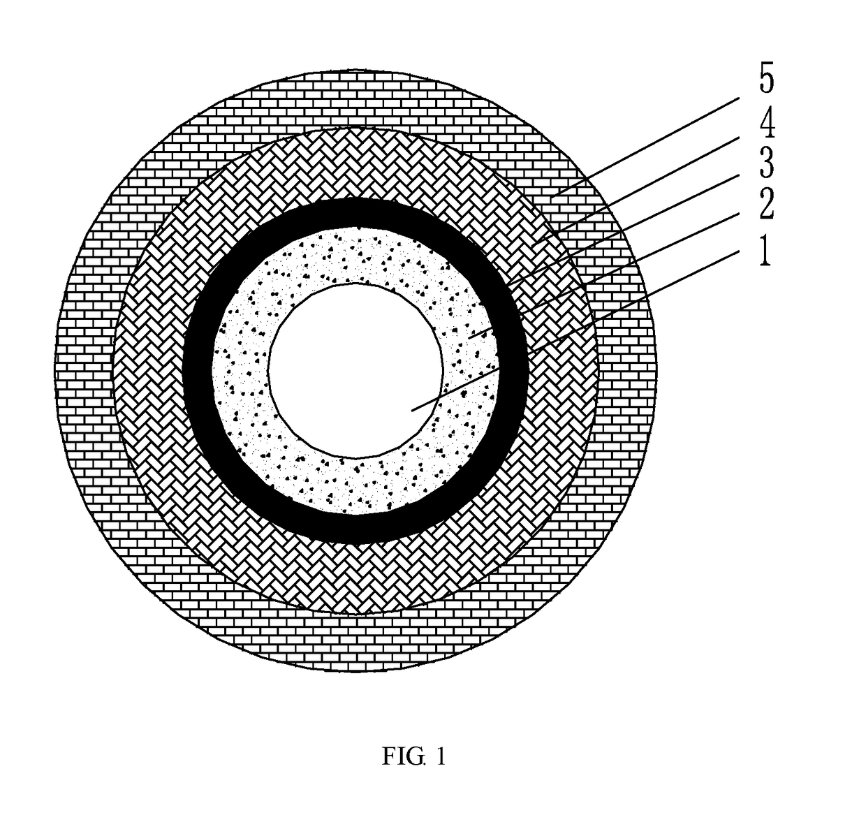
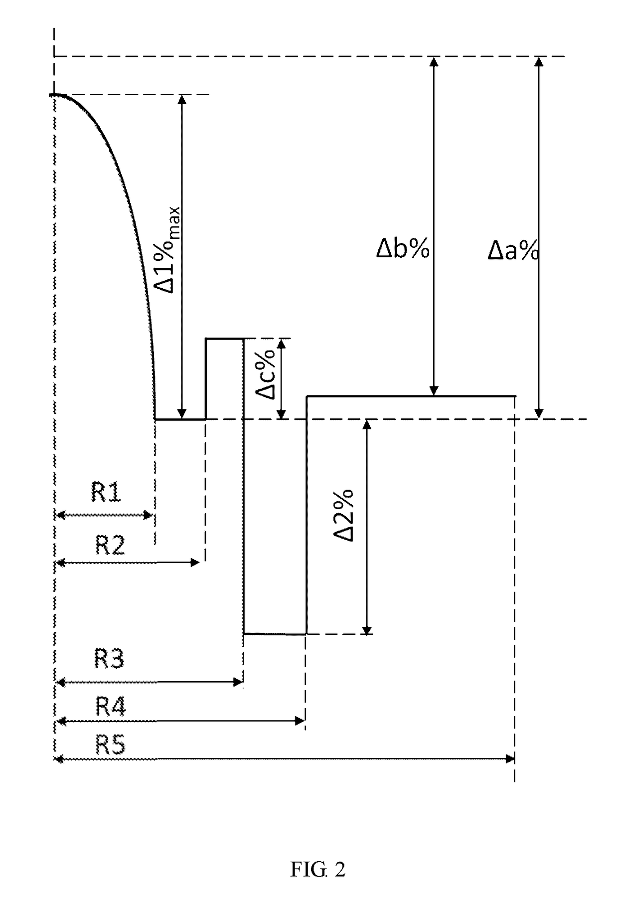
A low-loss few-mode fiber relates to the technical field of optical communications and related sensing devices, and includes, from inside to outside, a core layer (1), a fluorine-doped quartz inner cladding (2), a fluorine-doped quartz second core layer (3), a fluorine-doped quartz depressed cladding (4) and a fluorine-doped quartz outer cladding (5); germanium element is not doped within the core layer (1), the refractive index of the core layer (1) is in gradient distribution, and the distribution is a power-exponent distribution; the maximum value of difference in relative refractive index between the core layer (1) and the fluorine-doped quartz inner cladding (2) is 0.3% to 0.9%; the relative refractive index difference of the fluorine-doped quartz inner cladding (2) with respect to synthetic quartz is −0.3% to −0.5%; the difference in relative refractive index between the fluorine-doped quartz second core layer (3) and the fluorine-doped quartz inner cladding (2) is 0.05% to 0.2%; the difference in relative refractive index between the fluorine-doped quartz depressed cladding (4) and the fluorine-doped quartz inner cladding (2) is −0.1% to −0.5%; the relative refractive index difference of the fluorine-doped quartz outer cladding (5) with respect to synthetic quartz is −0.3% to −0.5%. The transmission loss of optical signals of the linear polarization modes that are supported by the few-mode fiber and the relay cost are reduced.

Description

TECHNICAL FIELD[0001]The present invention relates to the technical field of optical communications and related sensing devices, and more particularly to a low-loss few-mode fiber.BACKGROUND ART[0002]The data communications over fiber-optic networks continue to grow exponentially. In order to meet this need, multiplexing technology has been developed to allow multiple scattered data flows to share the same fibers, thus greatly increasing the traffic of each fiber.[0003]In the optical fiber industry, the current research and development focus mainly on DWDM (Dense Wavelength Division Multiplexing). DWDM is one of multiplexing technology in which multiple data channels are assigned to respective wavelengths within a certain operating bandwidth. Data channels are combined with the basic mode (LP01) of single-mode fibers for transmission, and when arriving at their respective destinations, they are returned to separation channels respectively.[0004]In a DWDM-based transmission system, t...

Claims


Application Information

Patent Timeline
IPC IPC(8): G02B6/036G02B6/028
CPCG02B6/0288G02B6/03666G02B6/028G02B6/036
Inventor MO, QIYU, HUANGCHEN, WENDU, CHENGYU, ZHIQIANGWANG, DONGXIANGCAI, BINGFENG
Owner FENGHUO COMM SCI & TECH CO LTD
Why Eureka
Try Eureka