Active front deflector

a technology of active front deflector and panel structure, which is applied in the direction of vehicle sub-unit features, vehicle body stabilisation, transportation and packaging, etc., can solve the problems of not meeting desired requirements, conventional structures such as fixed panels or fixed air deflectors/dams using flexible materials, and the loss of aerodynamic efficiency of vehicles, so as to improve ground clearance, improve airflow, and improve aerodynamics

Active Publication Date: 2017-05-04
MAGNA EXTERIORS INC
View PDF24 Cites 48 Cited by
  • Summary
  • Abstract
  • Description
  • Claims
  • Application Information

AI Technical Summary

Benefits of technology

[0006]There is provided an aerodynamic surface which improves aerodynamics when deployed and is retractable out of the way to return the vehicle to its initial design intent. The present invention is directed to an active front deflector assembly having at least one actuator and at least one deflector panel coupled to at least one linkage assembly. The active front deflector assembly is retractable so that it does not compromise the vehicle capabilities for conditions such as during off roading or when added ground clearance is needed, and is deployable for normal driving conditions. When in the extended or deployed position, the deflector panel improves airflow under predetermined conditions. When in the retracted or stowed position, the deflector panel generally moves or folds out of the way toward under the vehicle to improve ground clearance.
[0007]The active front deflector assembly provides a fully deployable system with object detection, declutching to help prevent damage, e.g., to protect the deflector panel under higher predetermined loads, communication with the vehicle to determine proper deployment and function, and is suitable to meet automotive specifications and functionality. Utilizing the active front deflector system that deploys and retracts based on predetermined vehicle requirements provides valuable reduction in vehicle drag, thereby reducing emissions and improving fuel economy. Additionally, it allows for the system to retract so the vehicle can still meet ground clearances, ramp angles, off-road requirements, etc.
[0008]Motion of the deployable deflector is driven by the linkage assembly and the actuator that is clutchable and that has communication capability with the vehicle, e.g., to prevent damage to the active front deflector system. The deployable deflector panel allows for aerodynamic benefits without limiting the vehicle ground clearance at lower speeds and while off roading or other predetermined conditions. The system does not require manual deployment and is only utilized when necessary under predetermined conditions, e.g., vehicle speeds in the range of at least 30 miles per hour.

Problems solved by technology

There is a considerable loss of aerodynamic efficiency in vehicles, in particular, due to the airflow underneath and around a vehicle.
Conventional structures, such as fixed panels or fixed air deflectors / dams using flexible materials, are known and do not meet desired requirements, including, but not limited to, conventional structures do not provide an effective sealed and clutchable actuator with communication capability and life cycle durability, a system that is capable of object detection, or a system that is durable and aerodynamically effective.
These fixed air deflector / dams are still a compromise as they cannot be made to the optimum height without compromising specifications and comparisons to other vehicle capabilities.
Further, these air dams even when flexible are still damaged during off-roading or when added ground clearance is needed.
Another known problem is that vehicle aerodynamics are compromised by design to accommodate a wide range of driving conditions.
These conditions only account for a small portion of the vehicle life, resulting in compromised vehicle aerodynamics for the majority of miles driven.

Method used


Image

  • Active front deflector
  • Active front deflector
  • Active front deflector

Examples


Embodiment Construction

[0020]The following description of the preferred embodiment(s) is merely exemplary in nature and is in no way intended to limit the invention, its application, or uses.

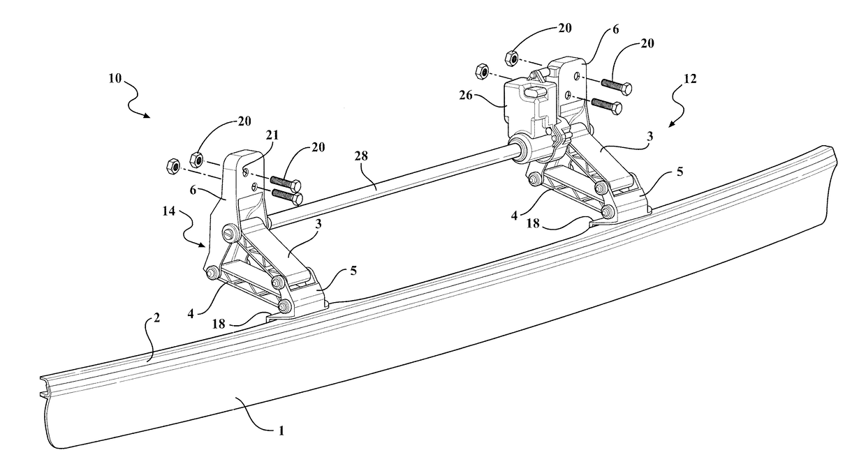
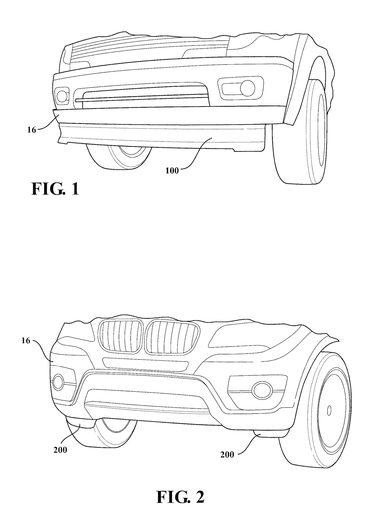
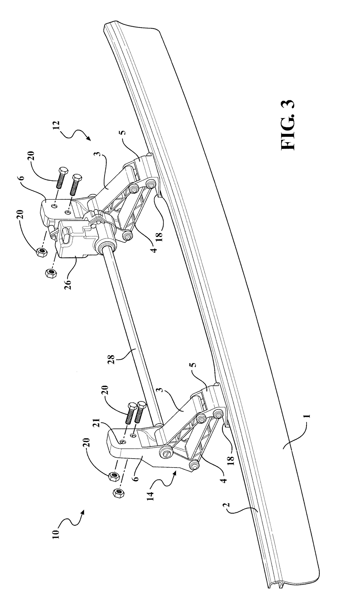
[0021]Referring to FIGS. 1-6 generally, in accordance with the present invention, there is provided an active front deflector assembly generally movable between a stowed position (or “retracted” position) and a deployed position (or “extended” position) under predetermined conditions. The active front deflector assembly provides an active full air deflector that deploys and retracts based on vehicle requirements. This allows for a deployment lower than fixed panel systems to significantly reduce drag, reduce emissions, improves fuel economy, (and / or improve active grille shutter performance when used in combination with the active front deflector assembly). Additionally, it allows for the system to retract so the vehicle can still meet ground clearances, ramp angles, off-road requirements, etc. In the event of impact ...


PUM


Abstract

An active front deflector assembly having a deployable deflector panel, linkage assemblies, and an actuator. The system deploys and retracts based on vehicle requirements, and, when deployed, interrupts air flow thereby improving the vehicle aerodynamics, reducing emissions and improving fuel economy. The deflector panel is retractable so the vehicle meets ground clearances, ramp angles, off-road requirements, etc. The deflector panel is also both rigid and semi-rigid to absorb impact energy. The linkage assemblies are coupled to the deflector panel and a drive shaft connected to the actuator. The drive shaft transmits the drive from the actuator coupled to one linkage assembly to the other linkage assembly for moving the deflector panel between the deployed/retracted positions. The actuator is clutched to prevent damage to the system. The active front deflector assembly provides a fully deployable system with object detection, declutching of the actuator, and communication with the vehicle.

Description

CROSS-REFERENCE TO RELATED APPLICATIONS[0001]This application claims the benefit of U.S. Provisional Application No. 62 / 010,825, filed Jun. 11, 2014. The disclosure of the above application is incorporated herein by reference.FIELD OF THE INVENTION[0002]The present invention relates to a panel structure of an active front deflector system for automotive applications.BACKGROUND OF THE INVENTION[0003]There is a considerable loss of aerodynamic efficiency in vehicles, in particular, due to the airflow underneath and around a vehicle. Conventional structures, such as fixed panels or fixed air deflectors / dams using flexible materials, are known and do not meet desired requirements, including, but not limited to, conventional structures do not provide an effective sealed and clutchable actuator with communication capability and life cycle durability, a system that is capable of object detection, or a system that is durable and aerodynamically effective. These fixed air deflector / dams are ...

Claims


Application Information

Patent Timeline
Patent Type & Authority Applications(United States)
IPC IPC(8): B62D35/00B62D35/02
CPCB62D35/005B60Y2400/411B60Y2300/52B62D35/02B62D37/02Y02T10/82B62D35/002
Inventor POVINELLI, ANTHONY J.MATTHEWS, MARTIN R.MANHIRE, JEFFREY B.
Owner MAGNA EXTERIORS INC
Why Eureka
Try Eureka