Parking position

Active Publication Date: 2017-05-04
KONGSBERG MARITIME SWEDEN AB
View PDF2 Cites 21 Cited by
  • Summary
  • Abstract
  • Description
  • Claims
  • Application Information

AI Technical Summary

Benefits of technology

[0011]Various aspects provide for “parking” an apparatus in a “parking position.” A parking position may be a configuration of an apparatus that minimizes environmental damage associated with a surface degradation process (e.g., marine growth, corrosion, wear, and the like) resulting from exposure to an environment during periods of inactivity. A parking

Problems solved by technology

In not being needed for normal operation, the parked configuration may result in dama

Method used


Image

  • Parking position
  • Parking position
  • Parking position

Examples


Embodiment Construction

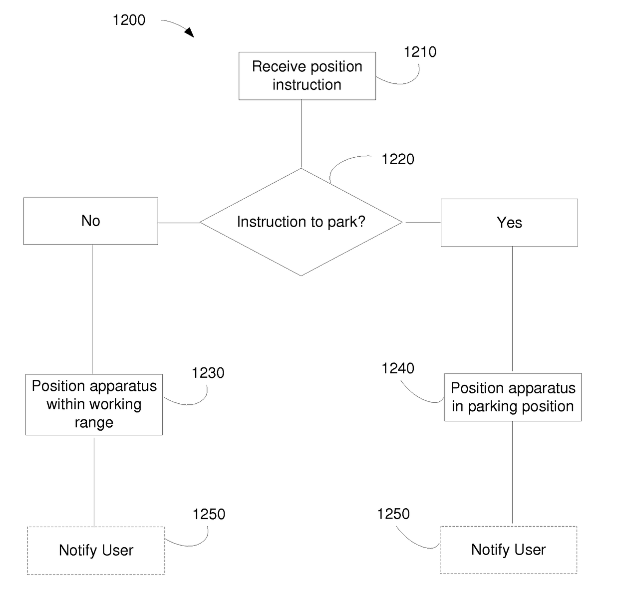
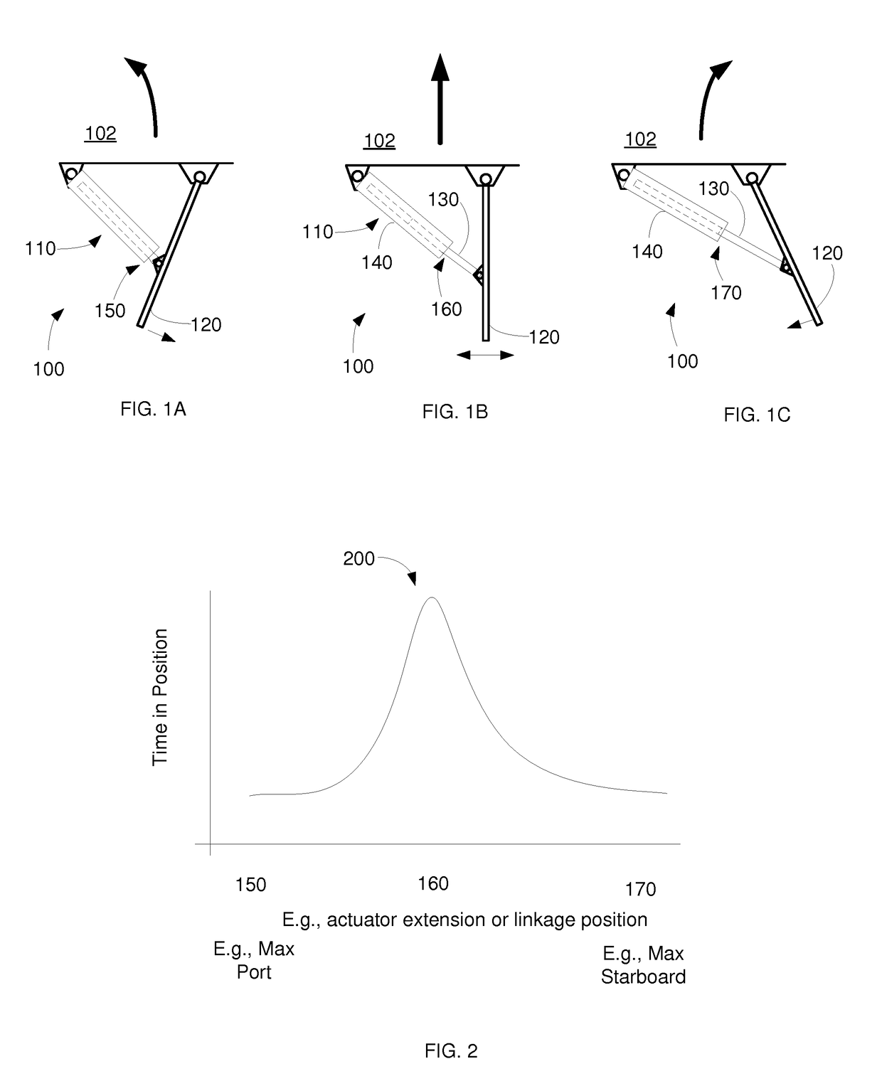
[0034]Various aspects may reduce damage of various systems, particularly localized damage of contact areas (e.g., wear of parts moving against each other). Damage of a surface may include surface corrosion, crevice corrosion, galvanic corrosion, film deposition, marine growth (e.g., living cells), dissolution of at least a portion of a surface, and the like. Equipment problems may be minimized by restricting the damage to an area that is seldom, or even never, used in normal operation. Damage may be restricted to such an un-needed area by positioning an apparatus in a “parking position.”

[0035]A parking position for an apparatus may be a configuration in which it is desirable to leave the apparatus during periods of inactivity. In some embodiments, various components (e.g., cylinders, linkage, shapes, sizes, clearances, dimensions, tolerances, and the like) are designed to incorporate an extended or additional range of motion that extends beyond that range of motion needed for normal...


PUM


Abstract

Various aspects provide for “parking” an apparatus in a “parking position.” A parking position may be a configuration of an apparatus that minimizes damage resulting from extended exposure during periods of inactivity. An apparatus may comprise a marine apparatus, which may be configured to be disposed in an environment comprising saltwater, salty air, brackish water, freshwater, and the like. An apparatus may comprise a propulsion system (e.g., for a ship) and/or a steering system. Some aspects include a water jet based propulsion system having a scoop and a nozzle operable to redirect the water jet, providing a range of forward/backward and port/starboard thrusts. A control cylinder and/or a linkage may be parked in a configuration that segregates damage incurred during periods of inactivity to portions of an apparatus not needed for normal operation.

Description

BACKGROUND[0001]1. Technical Field[0002]The present invention relates generally to reducing degradation of surfaces, and more particularly to wear associated with localized damage of contact areas.[0003]2. Background[0004]Many surfaces are damaged by processes such as corrosion, deposition, film formation, growth of organisms, dissolution of passivating layers, and the like (hereinafter: damage processes). In some cases, damage may be caused by the process per se. In some cases, a product of the process (e.g., a particles of metal, oxide, a hydroxide, or salt) may cause damage (e.g., if the product of the process abrades or contaminates parts of the system). Some degradation processes (e.g., galvanic and / or crevice corrosion) may be localized, and may be associated with a contact area between different components. When damaged, this contact area may perform poorly.[0005]Marine systems may be susceptible to degradation associated with seawater, particularly corrosion and biological p...

Claims


Application Information

Patent Timeline
IPC IPC(8): B63H11/11B63B59/08
CPCB63B59/08B63H11/11B63H25/26B63H25/48F15B11/121F15B15/1461G05G5/05F15B2211/865F15B2211/85F15B2211/7054B63H11/107B63H25/22B63H11/01G05D1/0206B63G8/001B63G8/08B63G2008/005B63H11/02B63H21/17F15B11/12F15B20/00F15B21/02G05D1/0011
Inventor FORSLUND, MICHAELJOHANSSON, JONAS
Owner KONGSBERG MARITIME SWEDEN AB
Why Eureka
Try Eureka