Vapor chamber and manufacturing method thereof

a technology of vapor chamber and manufacturing method, which is applied in the direction of manufacturing tools, soldering devices, light and heating equipment, etc., can solve the problems of poor heat conductivity, high manufacturing cost, and large amount of heat generated, and achieve the effect of increasing the return speed of working fluid

Inactive Publication Date: 2017-05-04
TAIWAN MICROLOOPS CORP
View PDF4 Cites 30 Cited by
  • Summary
  • Abstract
  • Description
  • Claims
  • Application Information

AI Technical Summary

Benefits of technology

[0010]Advantages achieved by the present invention are as follows: the returning speed of the working fluid is able to be increased through the capillary structure being in contact with the

Problems solved by technology

With the increasing calculation speed of an electronic component, massive amount of heat is generated.
However, there are still rooms to improve the heat conducting performance, the production cost and the manufacturing process for the vapor chamber.
However, for the manufacturing method of the conventional vapor chamber and the manufactured product, a heat conducting effect is provided but following disadvanta

Method used


Image

  • Vapor chamber and manufacturing method thereof
  • Vapor chamber and manufacturing method thereof
  • Vapor chamber and manufacturing method thereof

Examples


Embodiment Construction

[0020]Preferred embodiments of the present invention will be described with reference to the drawings.

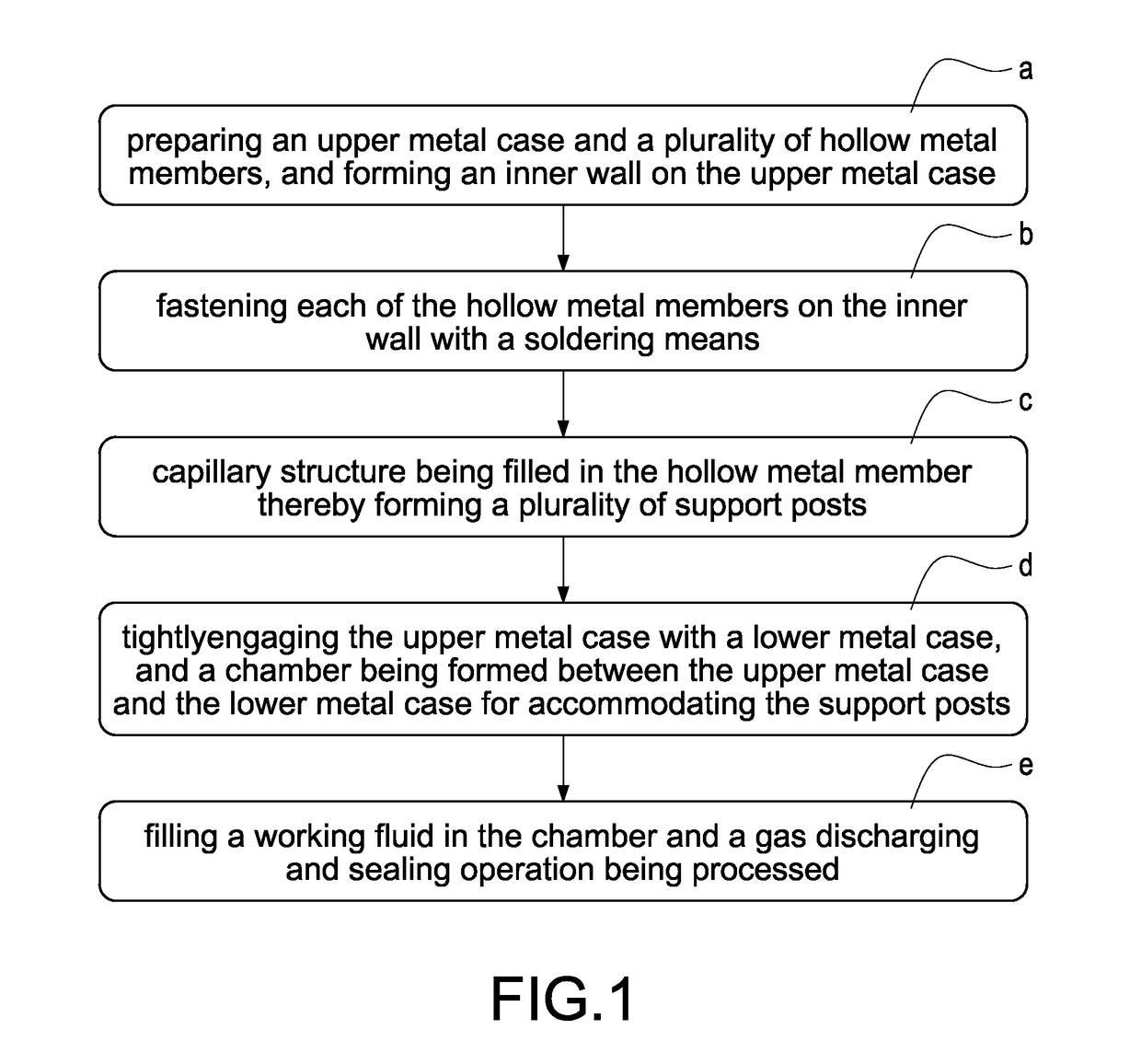
[0021]Please refer from FIG. 1 to FIG. 5, the present invention provides a manufacturing method of a vapor chamber, which includes the steps of:

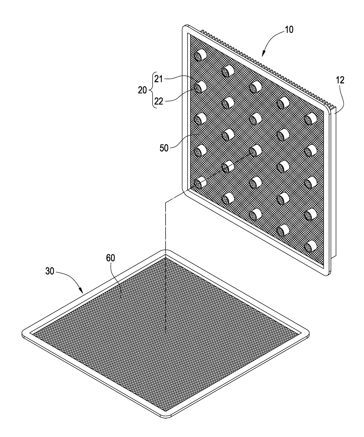
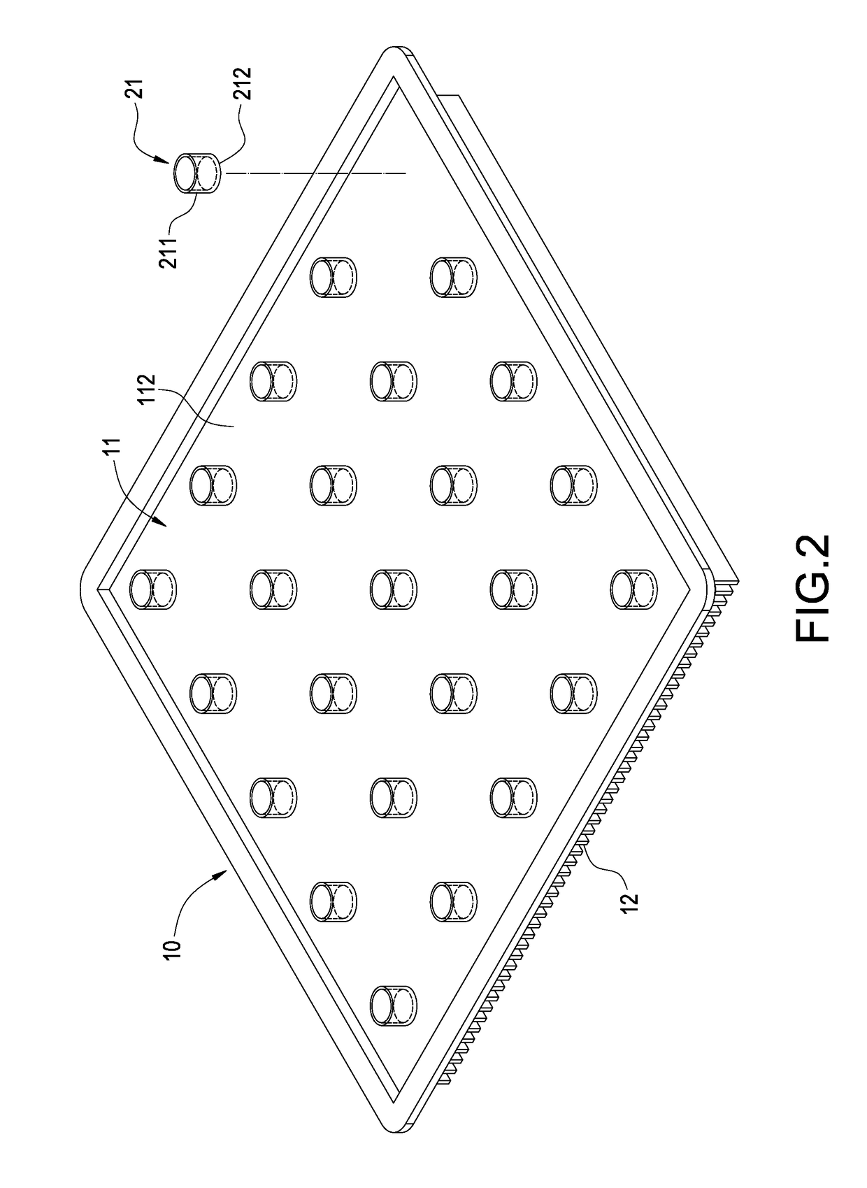
[0022]a step a) preparing an upper metal case 10 and a plurality of hollow metal members 21,

[0023]and forming an inner wall 112 on the upper metal case 10; in this step, the upper metal case 10 can be made of an electric conductive material such as copper, aluminum or an alloy thereof, and the upper metal case 10 mainly includes a rectangular substrate 11 and a plurality of heat dissipation fins 12, the substrate 11 is formed with an outer surface 111 and the inner surface 112 at the back side of the outer surface 111, each of the heat dissipation fins 12 is extended from the outer surface 111 and integrally formed, and the heat dissipation fins 12 can be formed with an extruding or cutting means and arranged with intervals. The hollow metal...


PUM

PropertyMeasurementUnit
Capillary waveaaaaaaaaaa

Abstract

In a vapor chamber and a manufacturing method thereof, the vapor chamber includes a lower metal case, an upper metal case, a plurality of support posts and a working fluid; the upper metal case is tightly engaged with the lower metal case, and a chamber is formed between the upper metal case and the lower metal case; the support posts are accommodated in the chamber and disposed between the upper metal case and the lower metal case, each of the support posts includes a hollow metal member and a capillary structure disposed inside the hollow metal member, and one end of the hollow metal member is soldered and fastened on the upper metal case; and the working fluid is filled in the chamber. Accordingly, advantages of simplifying manufacturing process, shortening manufacturing time and ensuring the quality of the vapor chamber to be stable can be achieved.

Description

BACKGROUND OF THE INVENTION[0001]Field of the Invention[0002]The present invention relates to a vapor chamber, especially to a vapor chamber used in an electronic component generating heat and a manufacturing method thereof.[0003]Description of Related Art[0004]With the increasing calculation speed of an electronic component, massive amount of heat is generated. For effectively dissipating the massive amount of heat, the skilled people in the art have developed a vapor chamber which has good heat conducting performance and has been wildly applied. However, there are still rooms to improve the heat conducting performance, the production cost and the manufacturing process for the vapor chamber.[0005]A manufacturing method of a conventional vapor chamber is to adhere an upper capillary tissue on an upper case then convey into a heater for thermal combination, then adhere a lower capillary tissue on a lower case then convey into a heater for thermal combination, a support structure is d...

Claims


Application Information

Patent Timeline
IPC IPC(8): F28D15/04B23P15/26
CPCF28D15/04B23P2700/09B23P15/26F28F2225/00B23K1/0012B23K1/19B23K35/00B23K35/0222F28D15/0233F28D15/046F28F2240/00B23K2101/12B23K2101/14B23K2101/36B23K2103/10B23K2103/12
Inventor LIN, CHUN-HUNG
Owner TAIWAN MICROLOOPS CORP
Why Eureka
Try Eureka