Apparatus, Systems and Methods for Point Cloud Generation and Constantly Tracking Position

Active Publication Date: 2017-05-04
ROBOTIC PARADIGM SYST LLC
View PDF0 Cites 39 Cited by
  • Summary
  • Abstract
  • Description
  • Claims
  • Application Information

AI Technical Summary

Benefits of technology

The present invention satisfies the need for apparatus, systems, and methods that can independently track the position of an RFLD and produce point clouds from RFLD to create maps of structures. The apparatus, systems, and methods can operate in real-time and are self-contained to perform these methods. The system can collect accurate scans of indoor spaces quickly and at a low cost. The system can move quickly through interior spaces and accommodate obstacles with its scanning device. The system can also collect digital, video, and audio information and post process it into useful forms like floor plans and physical layouts. The results can be inserted into various types of multi-media like smart phones and web browsers.

Problems solved by technology

A difficulty arises, however, when LIDAR is to be used in this way where GPS signals are not available.
This type of solution is not satisfactory for many applications, however, because the positioning of markers at precisely known locations is time consuming and, for large or complex structures, may require very large numbers of transmitters.
The accuracy of this system and method is limited, however, in part because errors in determining the position of the range-finder accumulate quickly over time.
This, in turn, limits the accuracy of a map resulting from the incorporation of inaccurate position data by the processor.
One significant limitation of this system and method is that the corner features required for the method must be known a priori from building blueprints or from another source, which limits their use to locations for which maps, blueprints, or other detailed position data is available.
This process requires significant computing power and does not provide the speed or accuracy of systems using markers of known reference locations.
Unfortunately, the accuracy of the pose calculated in this way is limited because of an accumulation of relatively small errors over time that result in large errors in the calculated pose.
Existing technologies and services for capturing data and rendering a layout of a building interior are relatively expensive or slow or both.
Technologies that provide very accurate results are expensive and slow.
Many are too bulky or fragile to be portable and the techniques have not been developed that support localizing, or determining the position of the equipment as it moves.
Scanning large volume areas such as millions of square feet in 6-10 hours at a reasonable cost is currently not possible.
In both cases, the scanning process is time consuming and a fixed or limited height of scanning limits coverage.
In the case of a moving cart, obstacles such as office cubicles have to be navigated to expose all interior spaces to the laser scan, which also slows the process.

Method used


Image

  • Apparatus, Systems and Methods for Point Cloud Generation and Constantly Tracking Position
  • Apparatus, Systems and Methods for Point Cloud Generation and Constantly Tracking Position
  • Apparatus, Systems and Methods for Point Cloud Generation and Constantly Tracking Position

Examples


Embodiment Construction

[0029]All art specific terms used herein are intended to have their art-accepted meanings in the context of the description unless otherwise indicated. All non art specific terms are intended to have their plain language meaning in the context of the description unless otherwise indicated.

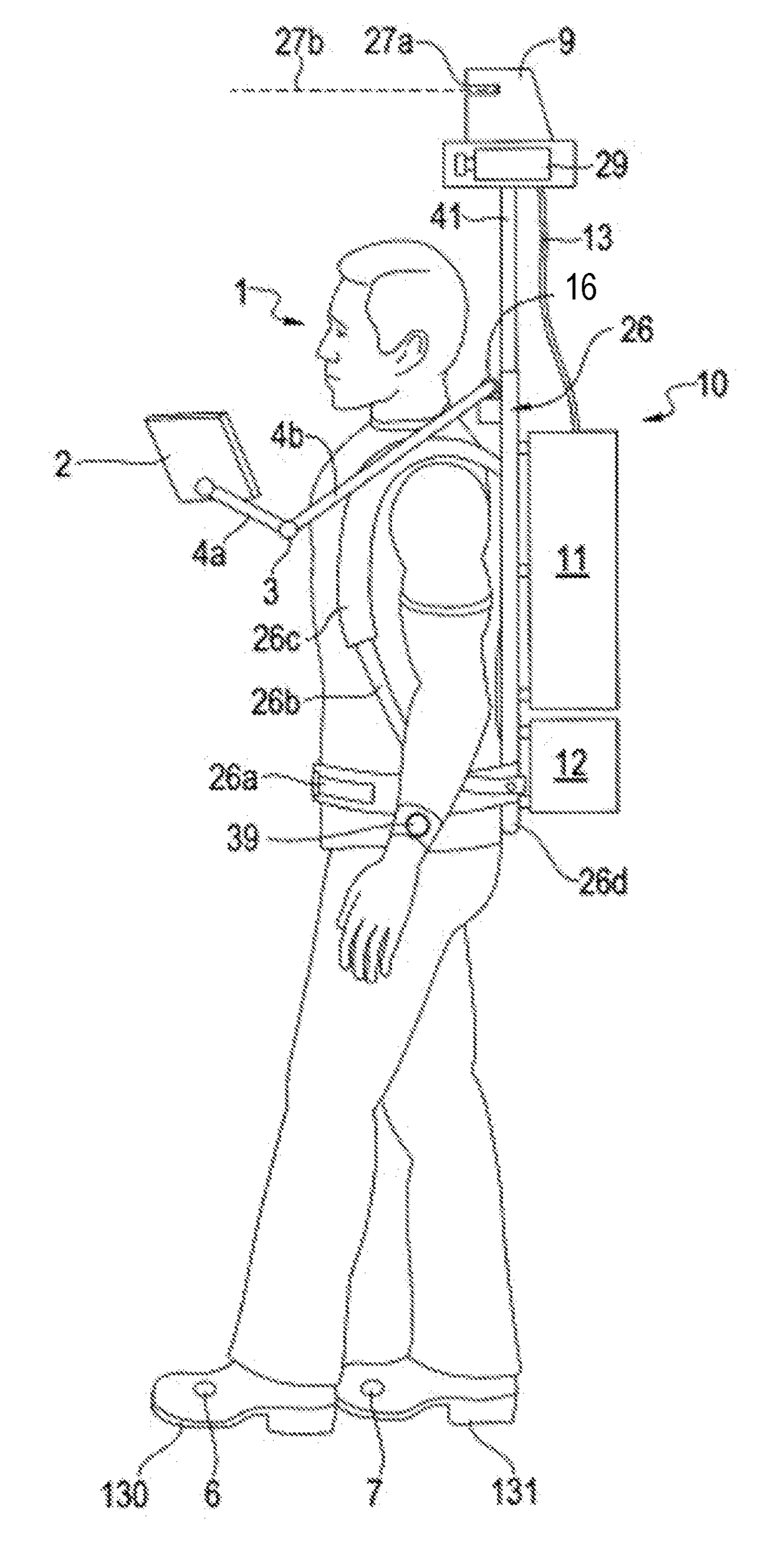
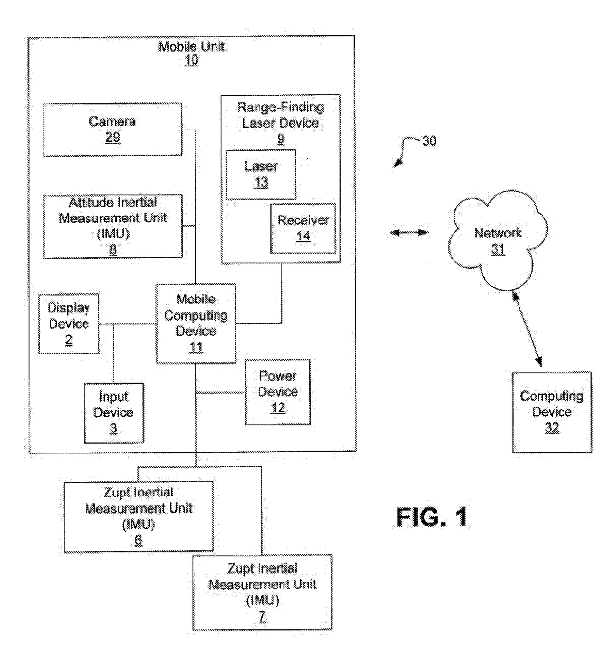
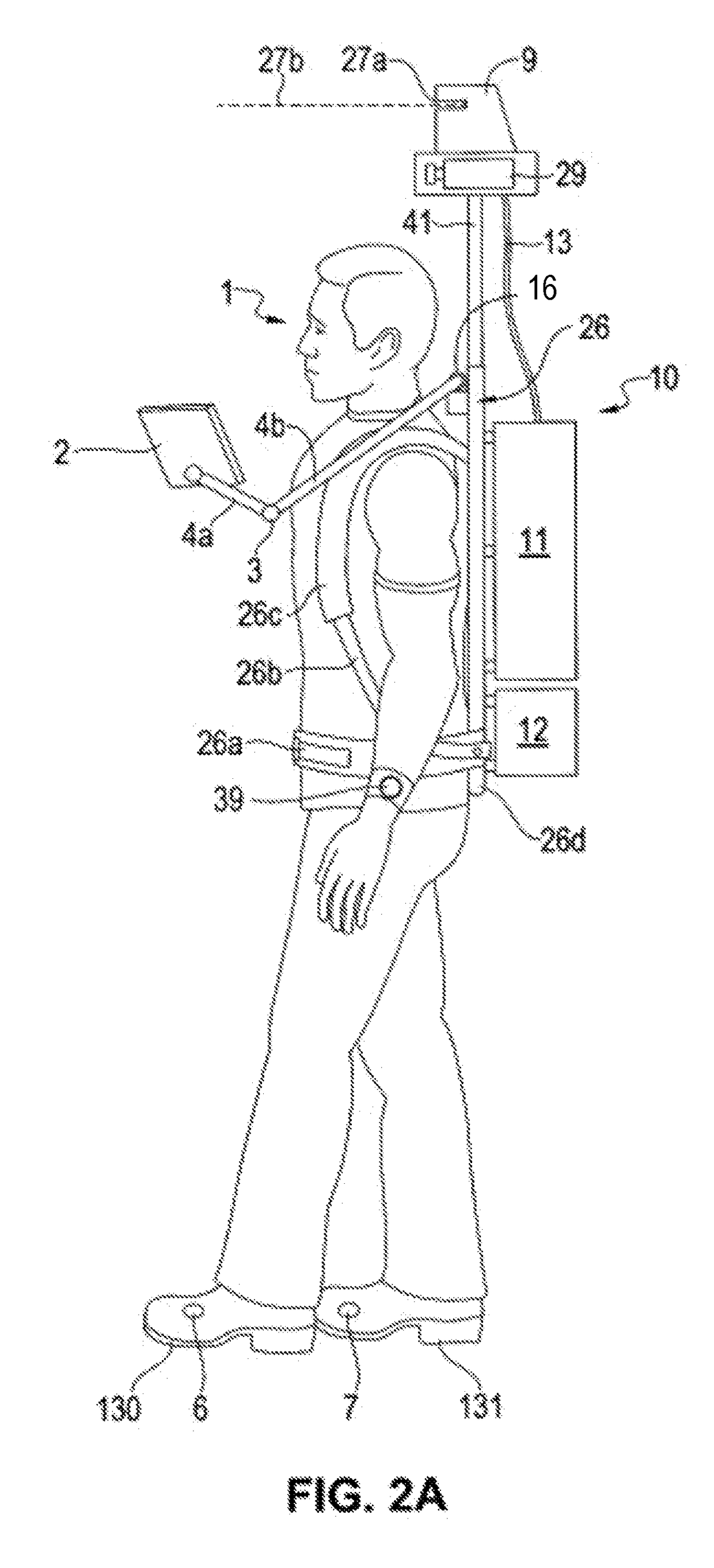
[0030]As used herein, the “pose” of an object refers the the position and orientation of the object in space at a given time. The position of the object may be described using a coordinate system, such as a Cartesian coordinate system. The orientation may be described, for example, in terms of pitch, roll, and yaw.

[0031]An incremental scan matcher pose is derived through a scan matching process, where successive laser scans are compared using a pattern matching or scan matching technique and the difference in orientation and position offset are computed. The difference is known as the change in pose, or incremental pose.

[0032]A point cloud is a set of information that represents Cartesian coordinat...


PUM


Abstract

A system having a range-finding laser device (RFLD) is configured to be coupled to an operator performs scans producing range and angle data points on surrounding structures. An attitude inertial measuring unit (IMU) attached to the RFLD measures pitch and roll of the RFLD and at least one zero-velocity update (zupt) IMU coupled to the operator is used to estimate the position, velocity and yaw of the operator. The system has computer logic that transforms data points from sensor frames of reference to a global frame of reference and merges transformed data points in a point cloud that can be used to generate images of scanned environments on a display.

Description

CROSS-REFERENCE TO RELATED APPLICATIONS[0001]This application is a Continuation-in-Part of U.S. application Ser. No. 13 / 723,698 filed Dec. 21, 2012, which claims priority to U.S. Provisional Application Ser. No. 61 / 578,375 filed Dec. 21, 2011, both of which are incorporated herein by reference in their entirety.BACKGROUND OF THE INVENTION[0002]Field of the Invention[0003]The present invention relates to the collection of data from range-finding laser devices (RFLDs), such as those used for Light Detection and Ranging (LIDAR) applications, to generate point clouds capable of creating maps of and / or within structures. The present invention additionally relates to accurately tracking the position of a RFLD using a Simultaneous Localization and Mapping (SLAM) process. The invention relates to apparatus, systems, and methods for collecting and processing RFLD data to generate a map image and to apparatus, systems, and methods for tracking the position of a RFLD device.[0004]Description o...

Claims


Application Information

Patent Timeline
IPC IPC(8): G01S17/87G01S17/42G01S7/481G01C3/08G01S17/875G01S17/86G01S17/89
CPCG01S17/875G01S7/4817G01S17/42G01C3/08G01S17/50G01S17/89G01C15/002G01S17/86
Inventor CODDINGTON, TIMOTHYGILBERT, LYNN CODDINGTON
Owner ROBOTIC PARADIGM SYST LLC
Why Eureka
Try Eureka