Mechanical Bar Conveying Device

a conveying device and mechanical bar technology, applied in the field of vehicle parts manufacturing, can solve the problems of high risk of industrial accidents, complex design, and relatively high maintenance cost, and achieve the effects of simple mechanical structure, stable clamping operation, and convenient us

Active Publication Date: 2017-05-04
CITIC DICASTAL
View PDF0 Cites 18 Cited by
  • Summary
  • Abstract
  • Description
  • Claims
  • Application Information

AI Technical Summary

Benefits of technology

[0013]The device of the invention has the following advantages: the mechanical bar conveying device consists of three ball screw rods vertical to one another, a rack-and-pinion mechanism and a claw portion combined mechanism at the bottom; It automatically calculates the pick-up position and travel speed of different specifications of bars (such as of 8 inches, 9 inches and 10 inches), detects the pick-up force moment in real time, does not need the participation of operators, has simple mechanic

Problems solved by technology

However, the existing conveying facilities often have the following problems: (1) complex design and relatively high maintenance cost; (2) poor adaptability of the mechanism for different diameters of bars,

Method used


Image

  • Mechanical Bar Conveying Device
  • Mechanical Bar Conveying Device
  • Mechanical Bar Conveying Device

Examples


example 1

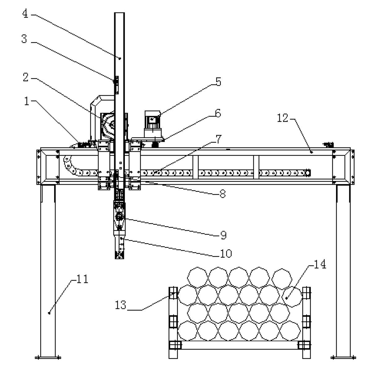
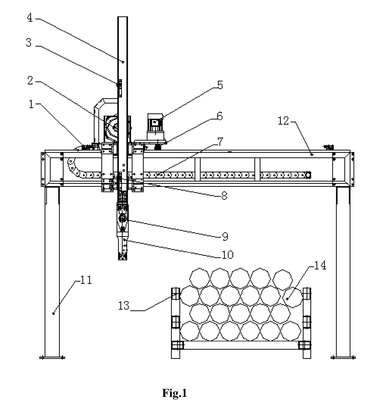
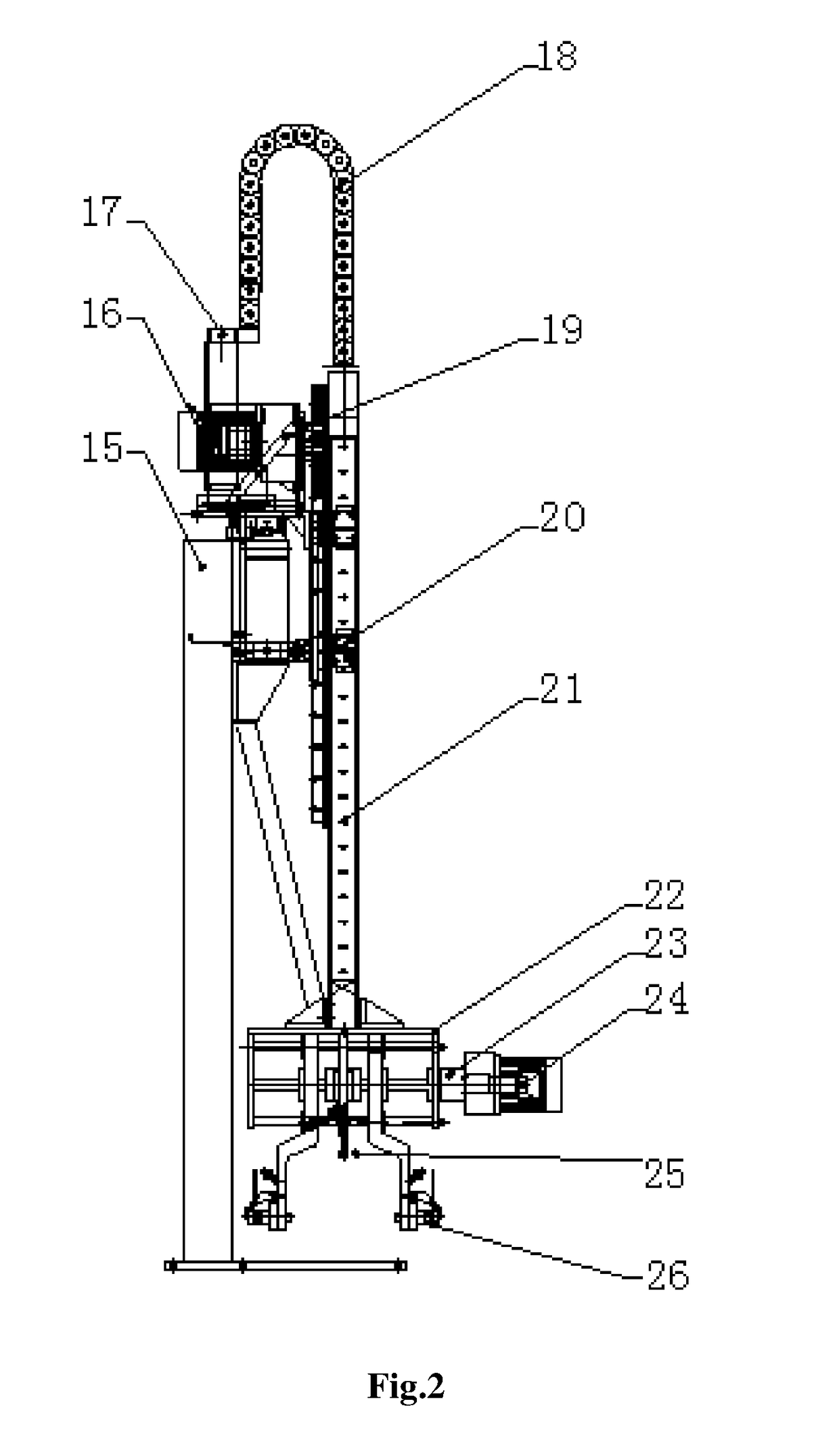
[0018]The mechanical bar conveying device essentially consists of a frame connection portion, a vertical movement portion, a horizontal movement portion, a mechanical manipulator portion and a man machine interaction display portion, including three screw rods vertical to one another, a rack and a mechanical claw at the bottom; it automatically calculates the pick-up position and travel speed of different specifications of bars (such as of 8 inches, 9 inches and 10 inches), detects the pick-up force moment in real time, does not need the participation of operators, has simple mechanical structure and stable bar clamping operation, and is convenient to use.

[0019]Based on the exchange and communication with an upper computer, the mechanical bar conveying device obtains the diameters of a bar, determines the first bar positioning data, and calculates the difference in number between the odd and even layers of bars stacked, and relative positioning address data of each layer of bars and...


PUM


Abstract

The invention provides a mechanical bar conveying device consisting of a horizontal travel limiting device (1), a vertical axis servo reducer (2), a vertical descent depth detector (3), a vertical axis travelling mechanism (4), a horizontal axis servo reducer (5), a horizontal drive gear (6), a horizontal tow chain (7), a horizontal moving mechanism (8), a manipulator torque detector (9), a safety detection mechanism (10), a main frame (11), a horizontal frame (12), a vertical movement mechanism (16), a tow chain bracket (17), a tow chain (18), a vertical rack-and-pinion mechanism (19), a horizontal linear guide track (20), a vertical beam (21), a claw clamping mechanism (22), a claw ball screw (23), a manipulator servo reducer (24), a manipulator depth detector (25), and a claw and travel limiting combined mechanism (26). The device realizes automatic conveying of bars, and avoids the problems of manual conveying process, such as high environmental temperature, large intensity, low work efficiency and high risk of industrial accidents.

Description

[0001]This application claims priority from CN 201510732546.0, filed on Oct. 30, 2015, the entire content of which is incorporated herein by reference.TECHNICAL FIELD[0002]The invention relates to the vehicle parts manufacturing field, in particular to a mechanical bar conveying device.BACKGROUND ART[0003]In a wheel hub manufacturing plant, spin casting wheel hub bars are usually conveyed by men. For heavy weight of bars, bar conveying facilities are designed in the spin casting field. However, the existing conveying facilities often have the following problems: (1) complex design and relatively high maintenance cost; (2) poor adaptability of the mechanism for different diameters of bars, causing high risk of industrial accidents due to unstable clamping; (3) relatively low production efficiency of the existing facilities and failure to meet the production requirements.[0004]The above problems cause[0005]Thus, there is an urgent need for a bar conveying facility in production to ove...

Claims


Application Information

Patent Timeline
IPC IPC(8): G05B19/402B66C1/42B66C5/02B66C19/00
CPCG05B19/402B66C19/00B66C1/42G05B2219/35581B62D65/00G05B2219/2637B66C5/02B66C1/425B66C17/04
Inventor LIU, TAOTAO
Owner CITIC DICASTAL
Why Eureka
Try Eureka