
Connector

a technology of connecting rods and connectors, applied in the direction of coupling devices, two-part coupling devices, electrical apparatus, etc., can solve the problems of micro short circuit, micro short circuit, and blown service input/output interfaces for charging, etc., to increase the volume of battery electricity, increase the effective area, and increase the effect of battery power

Active Publication Date: 2017-05-04
POLYTRONICS TECH
View PDF13 Cites 5 Cited by
  • Summary
  • Abstract
  • Description
  • Claims
  • Application Information

AI Technical Summary

Benefits of technology

The present invention provides a connector with a layered circuit substrate that can protect against short-circuit or micro short-circuit during battery charging or data transmission. The connector uses a PTC conductive composite material as the core of the layered circuit substrate to provide over-current and / or over-temperature protection. This prevents the connector and the electronic apparatus connected thereto from being blown due to heat caused by over-current. The PTC material layer as the core of the entire layered circuit substrate can use high-voltage withstanding material to enhance practicability and applicability. Sellers can easily identify whether buyasers use charging cables coming with the products of the sellers by inspecting whether PTC layered circuit substrates are used in the connectors, to avoid disputes of improper use after sale.

Problems solved by technology

During high power charging, connectors, e.g., USB, microUSB, or USB Type-C, serving as input / output interfaces for charging may be blown due to micro short-circuit.
Micro short-circuit may also occur if connectors are damaged or deformed due to plugging on a slant or violent plugging.
Micro short-circuit does not meet the criteria to trigger short-circuit protection, and thus a battery charger continuously outputs power which transforms into heat to heat up the connector and the battery charger.
As a consequence, the connector or the battery charger may have a malfunction or be burned out.
As mentioned above, it is more likely to cause malfunction or burnout of the USB cables because of large charging current and frequent plugging.
Most USB cables are not provided with protection devices.
Even if the USB cables are provided with protection devices, they are not able to sense micro short-circuit to trigger current reduction.
Therefore the USB cables, the associated connectors or electronic apparatuses may suffer breakdown or burnout issues, raising safety concerns to the users.

Method used


Image

  • Connector
  • Connector
  • Connector

Examples


Embodiment Construction

[0029]The making and using of the presently preferred illustrative embodiments are discussed in detail below. It should be appreciated, however, that the present application provides many applicable inventive concepts that can be embodied in a wide variety of specific contexts. The specific illustrative embodiments discussed are merely illustrative of specific ways to make and use the invention, and do not limit the scope of the invention.

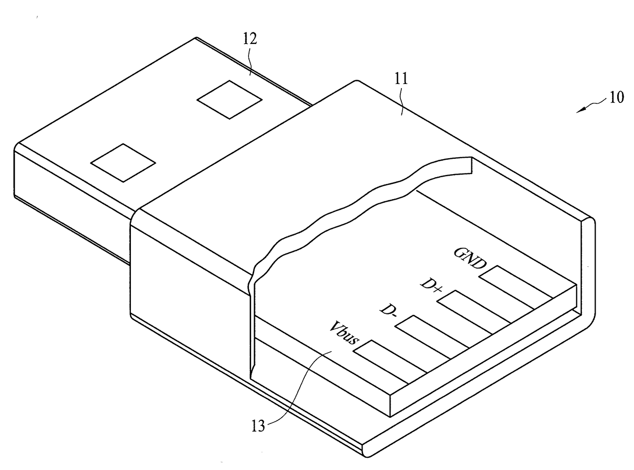
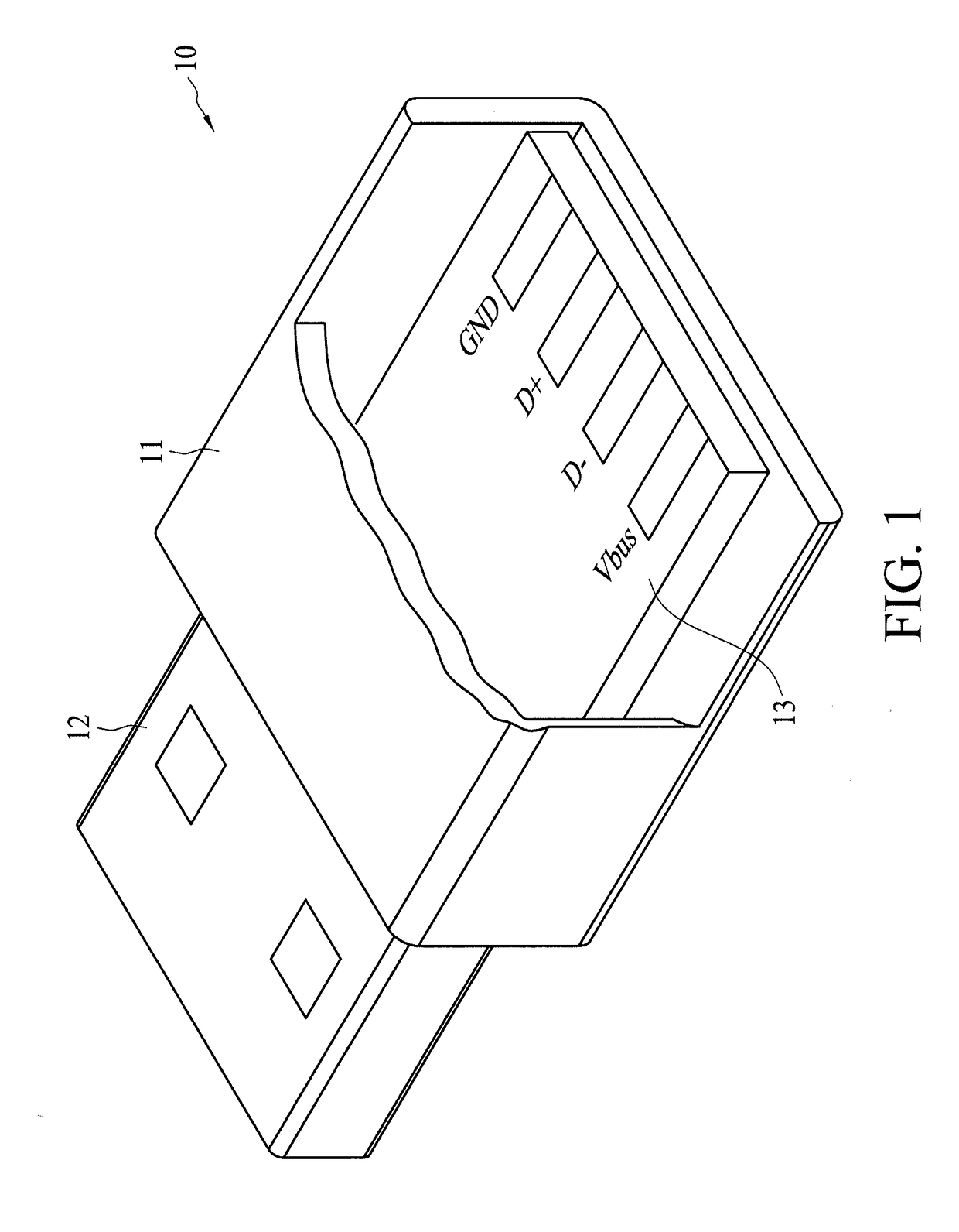
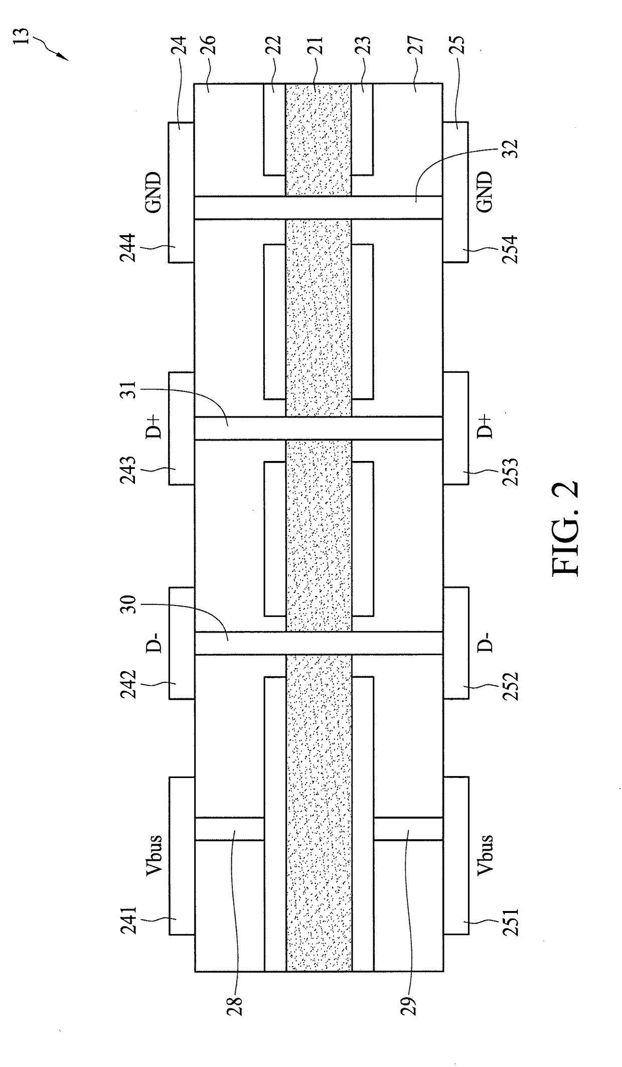
[0030]FIG. 1 shows a connector in accordance with an embodiment of the present application. The connector is exemplified by but not limited to a USB 2.0 connector. The connector 10 comprises a housing 11, a terminal 12 and a layered circuit substrate 13. The layered circuit substrate 13 has an end connecting to the terminal 12, and another end connecting to an electric wire or cable (not shown). The terminal 12 has plural pins electrically connecting to corresponding electrode pads Vbus, D−, D+ and GND of the layered circuit substrate 13. In compli...


PUM


Abstract

A connector comprises a terminal and a layered circuit substrate. The layered circuit substrate connects to an end of the terminal, and comprises a PTC material layer, a first electrode layer forming an upper layer of the layered circuit substrate, and a second electrode layer forming a lower surface of the layered circuit substrate. The PTC material layer is disposed between the first and second electrode layers. The first and second electrode layers comprise first and second electrode pads which connect to a power supply, and the PTC material layer electrically connects to the first and second electrode pads to form an electrically conductive path in which the PTC material layer serves as a PTC resistor in series connection between the first and second electrode pads. When an over-current or over-temperature event occurs in the electrically conductive path, the PTC resistor will trip to a high resistance state.

Description

BACKGROUND OF THE INVENTION[0001](1) Field of the Invention[0002]The present application relates to a connector, and more specifically, to a connector with over-temperature and over-current protections.[0003](2) Description of the Related Art[0004]With the development of mobile apparatuses, users require more functions. As such, electricity volume of a battery of a mobile apparatus becomes larger to meet the need of a larger screen size of the mobile apparatus, and high efficient quick charge technology is prevalent gradually. Therefore, high power battery charging is demanded. During high power charging, connectors, e.g., USB, microUSB, or USB Type-C, serving as input / output interfaces for charging may be blown due to micro short-circuit. In charging with a large current, with the increase of hot-plugging times, unexpected bodies such as hairs, metal scraps, liquids or coffee dregs may enter the connectors to incur micro short-circuit. Micro short-circuit may also occur if connecto...

Claims


Application Information

Patent Timeline
Patent Type & Authority Applications(United States)
IPC IPC(8): H01R13/68H01R13/717H01R13/66
CPCH01R13/68H01R13/7175H01R13/6616H01R13/6666H01R13/6683H01R13/713H01R24/60H01R2107/00
Inventor TSENG, CHUN TENGWANG, DAVID SHAU CHEW
Owner POLYTRONICS TECH
Learn More