Laser oscillation device for multiplexing and outputting laser light

a laser light and laser technology, applied in semiconductor laser arrangements, semiconductor lasers, manufacturing tools, etc., can solve the problems of high failure rate of laser oscillation devices, failure to perform stable output control,

Inactive Publication Date: 2017-05-04
FANUC LTD
View PDF11 Cites 7 Cited by
  • Summary
  • Abstract
  • Description
  • Claims
  • Application Information

AI Technical Summary

Benefits of technology

[0012]The present invention provides a laser oscillation device that can avoid concentration of a load on a specific light source during a low output instruction.

Problems solved by technology

However, if a minimum output of the resonators is no more than a value in which the rated output of the resonators is multiplied by a predetermined rate, for example, 10% of the rated output, i.e. 50 W (=500 W×10%), a stable output control fails to be performed.
Consequently, during the low output instruction, a load is concentrated on the specific light source, whereby the specific light source is apt to deteriorate and, as a result, a frequency of failures of the laser oscillation device also becomes high, which has been a problem.

Method used


Image

  • Laser oscillation device for multiplexing and outputting laser light
  • Laser oscillation device for multiplexing and outputting laser light
  • Laser oscillation device for multiplexing and outputting laser light

Examples


Embodiment Construction

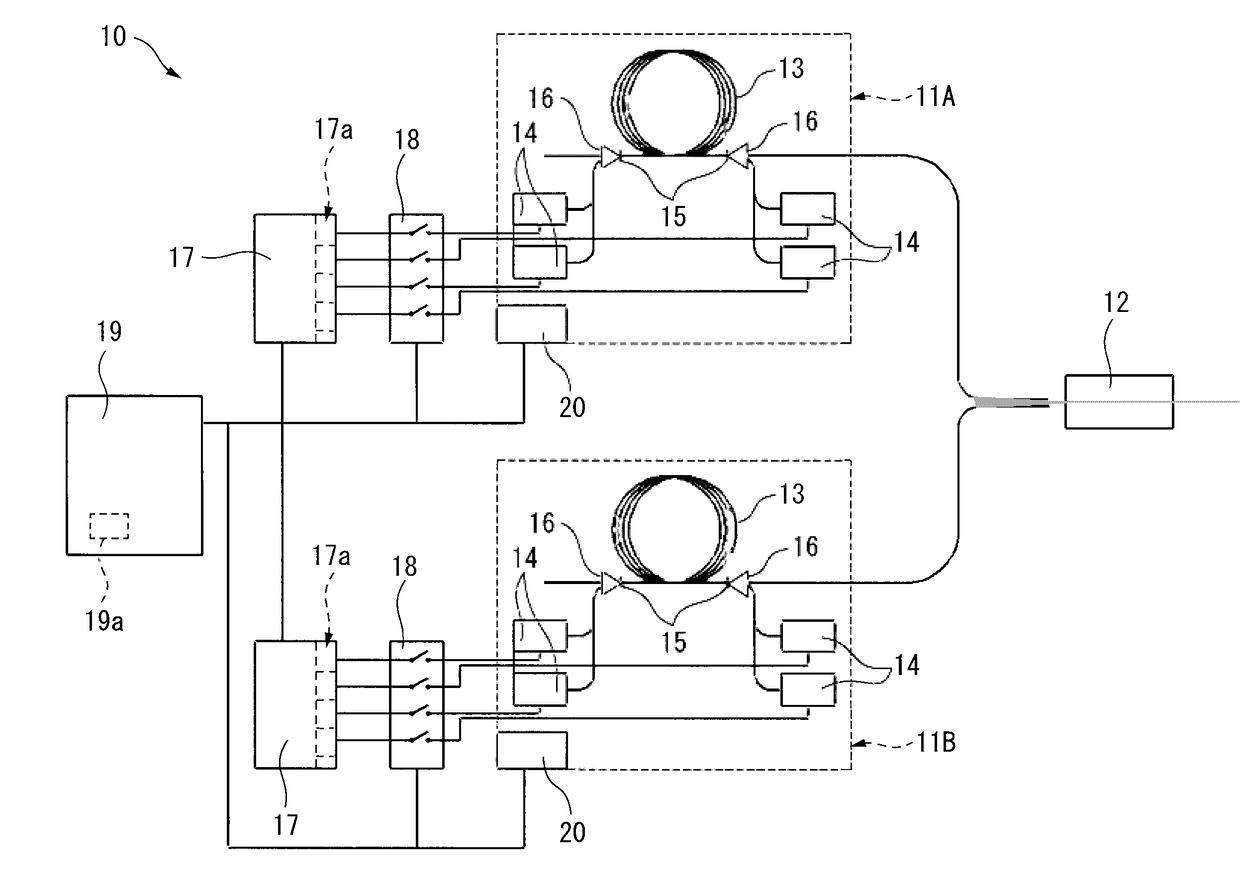
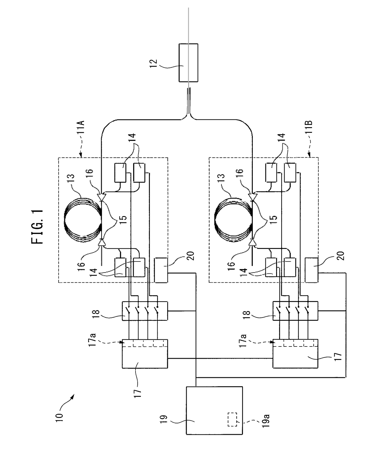
[0038]Next, embodiments of the present invention will be described with reference to the drawings. In the following figures, the same components and functions will be assigned the same reference signs. In addition, it is assumed that the elements denoted by the same reference signs in different drawings denote elements having the same functions. Moreover, in order to facilitate understanding, these figures are suitably changed in scale. Further, in the following, as a laser oscillation device, a fiber laser and a DDL will be described as an example, to which, however, the present invention is not limited.

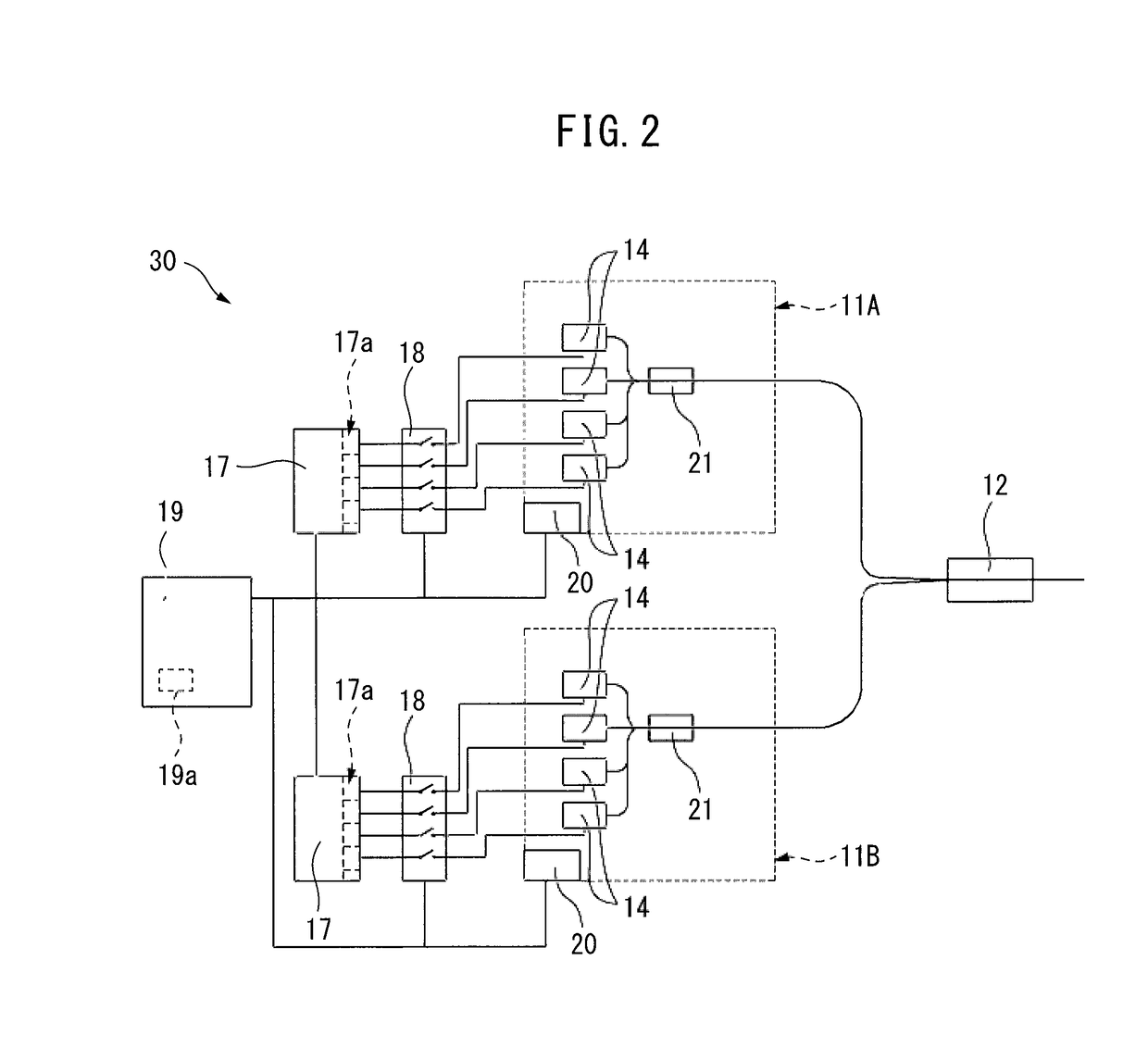
[0039]FIG. 1 is a block diagram illustrating a configuration of a laser oscillation device according to an embodiment of the present invention. FIG. 2 is a block diagram illustrating a modification of the laser oscillation device as illustrated in FIG. 1.

[0040]The laser oscillation device as illustrated in FIG. 1 is a fiber laser 10, and the laser oscillation device as illustrated i...


PUM

PropertyMeasurementUnit
currentaaaaaaaaaa
currentaaaaaaaaaa
drive timeaaaaaaaaaa

Abstract

A laser oscillation device herein cumulates a value in which a weighting coefficient determined according to a value of a current that has driven light sources is multiplied by a drive time of the light sources every time each of the light source is driven, and stores a cumulative value obtained from thus cumulating while allowing the same to correspond to each of the light sources. Then, an instruction unit of the laser oscillation device determines the number of the light sources to radiate according to an output range of a laser output instruction, and by the number determined, the light sources are configured to be selected in an order from the smaller cumulative value by a selection unit, and only the selected light sources are allowed to radiate by a current control unit.

Description

BACKGROUND OF THE INVENTION[0001]1. Field of the Invention[0002]The present invention. relates to a laser oscillation device that multiplexes and outputs laser light radiated from a plurality of light sources.[0003]2. Description of the Related Art[0004]Conventionally, a laser oscillation device has been applied to a laser processing device that cuts, welds, modifies a surface, marks, trims, etc., of a component. Recently, in order to enhance an output of a laser oscillation device, a laser oscillation, device that multiplexes and outputs laser light from a plurality of light sources, such as a fiber laser and a direct diode laser (hereinafter referred to as DDL), has been developed.[0005]The fiber laser includes a plurality of resonators having a plurality of semiconductor lasers for excitation that are the light sources as described above and an optical fiber for excitation, and multiplexes and outputs laser light from the plurality of resonators by a multiplexer. On the other han...

Claims


Application Information

Patent Timeline
Patent Type & Authority Applications(United States)
IPC IPC(8): H01S5/042H01S5/40H01S3/0941H01S5/06H01S3/067
CPCH01S5/042H01S5/0617H01S5/4025H01S3/09415H01S3/0675B23K26/0613H01S3/10069H01S3/2383H01S3/09408H01S5/06825H01S5/0683H01S5/4012H01S3/094011
Inventor SATO, TAKANORI
Owner FANUC LTD
Why Eureka
Try Eureka