Eureka AIR delivers breakthrough ideas for toughest innovation challenges, trusted by R&D personnel around the world.

Method and apparatus for calibrating a digitally controlled oscillator

Active Publication Date: 2017-05-04
NXP USA INC
View PDF3 Cites 6 Cited by
  • Summary
  • Abstract
  • Description
  • Claims
  • Application Information

AI Technical Summary

Benefits of technology

The present invention is about a way to calibrate a digitally controlled oscillator. It also includes a digital synthesizer that uses a digitally controlled oscillator. The invention helps to improve the accuracy and reliability of the digitally controlled oscillator. This can be useful in a variety of applications where the accurate control of oscillation is important.

Problems solved by technology

In applications such as automotive radar systems, phase noise introduced into the output frequency signal by the synthesizer is critical.

Method used


Image

  • Method and apparatus for calibrating a digitally controlled oscillator
  • Method and apparatus for calibrating a digitally controlled oscillator
  • Method and apparatus for calibrating a digitally controlled oscillator

Examples


Embodiment Construction

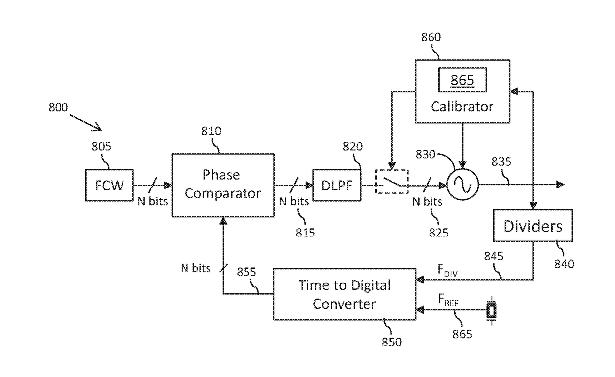
[0023]In accordance with some example embodiments of the present invention, there is provided a method of calibrating a digitally controlled oscillator (DCO). More specifically, during calibration of the DCO, it is proposed to calibrate, for each coarse tuning capacitive configuration, a resolution adjustment component of the fine tuning capacitive component of the DCO such that the fine tuneable ranges for consecutive coarse tuning capacitive bank configurations are aligned.

[0024]Advantageously, such a calibration process allows PVT variations etc. to be compensated for without the need for relying on error margins that waste control signals / codes for the fine tuning capacitive component. In particular, following such a calibration process, the full fine tuneable range of the DCO is used, and no control signals / codes are wasted on error margins. Consequently, the smallest achievable DCO LSB tuneable frequency step can be realized, and thus the minimum achievable frequency resolutio...


PUM


Abstract

A method of calibrating a digitally controlled oscillator (DCO). The method comprises configuring a fine tuning capacitive component of the DCO into a minimum capacitance configuration therefor, configuring a coarse tuning capacitive component of the DCO into a first configuration therefor and determining a resulting first output frequency of the DCO. The method further comprises configuring the coarse tuning capacitive component into a second configuration therefor, the second and first configurations of the coarse tuning capacitive component being capacitively increasing consecutive configurations respectively, configuring the fine tuning capacitive component into a maximum capacitance configuration therefor, determining control signal settings for a resolution adjustment component of the DCO that achieve a resulting output frequency of the DCO equal to the determined first output frequency, and generating calibration data for the second configuration of the coarse tuning capacitive component comprising the determined control signal settings for the resolution adjustment component.

Description

FIELD OF THE INVENTION[0001]This invention relates to a method and apparatus for calibrating a digitally controlled oscillator.BACKGROUND OF THE INVENTION[0002]In many applications, a digital synthesizer is implemented by way of a digital phase locked loop (DPLL) that is used to control a digitally controlled oscillator (DCO) to generate (synthesize) an output frequency signal. Such digital synthesizers provide the benefit of simplifying the integration of the synthesizer circuity within large scale integrated digital circuit devices, as compared with equivalent analogue synthesizers, thereby reducing size, costs, power consumption and design complexity. Furthermore, DPLLs intrinsically present lower phase noise than their analogue counterparts.[0003]In applications such as automotive radar systems, phase noise introduced into the output frequency signal by the synthesizer is critical. In the case of radar systems, the phase noise dictates the system's ability to distinguish between...

Claims


Application Information

Patent Timeline
IPC IPC(8): H03L7/099H03B5/04H03L7/18H03L7/093H03L7/091
CPCH03L7/0991H03L7/093H03B5/04H03L7/18H03L7/091H03B2201/0208H03L2207/06H03L2207/50H03L7/099H03B5/1265H03B5/1253H03B5/1228H03L7/12H03B5/1212
Inventor PAVAO MOREIRA, CRISTIANDOARE, OLIVIER VINCENTGOUMBALLA, BIRAMASALLE, DIDIER
Owner NXP USA INC
Why Eureka
Eureka Blog
Learn More