
Method for realizing integrated time stamp clock synchronous phase-locked loop

A technology of time synchronization and time stamping, which is applied in the field of digital phase-locked loops, and can solve problems such as the large increase in the size of the system clock module, the increase in system construction costs, and the complexity of system implementation

Inactive Publication Date: 2007-12-05
SOUTH CHINA UNIV OF TECH
View PDF3 Cites 35 Cited by
  • Summary
  • Abstract
  • Description
  • Claims
  • Application Information

AI Technical Summary

Problems solved by technology

The amount of clock drift directly limits the possible time synchronization accuracy
[0006] In a distributed system, if each node uses a high-stability clock, it will not only increase the construction cost of the system rapidly, but also bring additional implementation complexity to the system.
Even if a crystal oscillator with the most basic temperature compensation is used, the cost of the system clock will be greatly increased, and the size of the system clock module will also be greatly increased.

Method used


Image

  • Method for realizing integrated time stamp clock synchronous phase-locked loop
  • Method for realizing integrated time stamp clock synchronous phase-locked loop
  • Method for realizing integrated time stamp clock synchronous phase-locked loop

Examples


Embodiment Construction

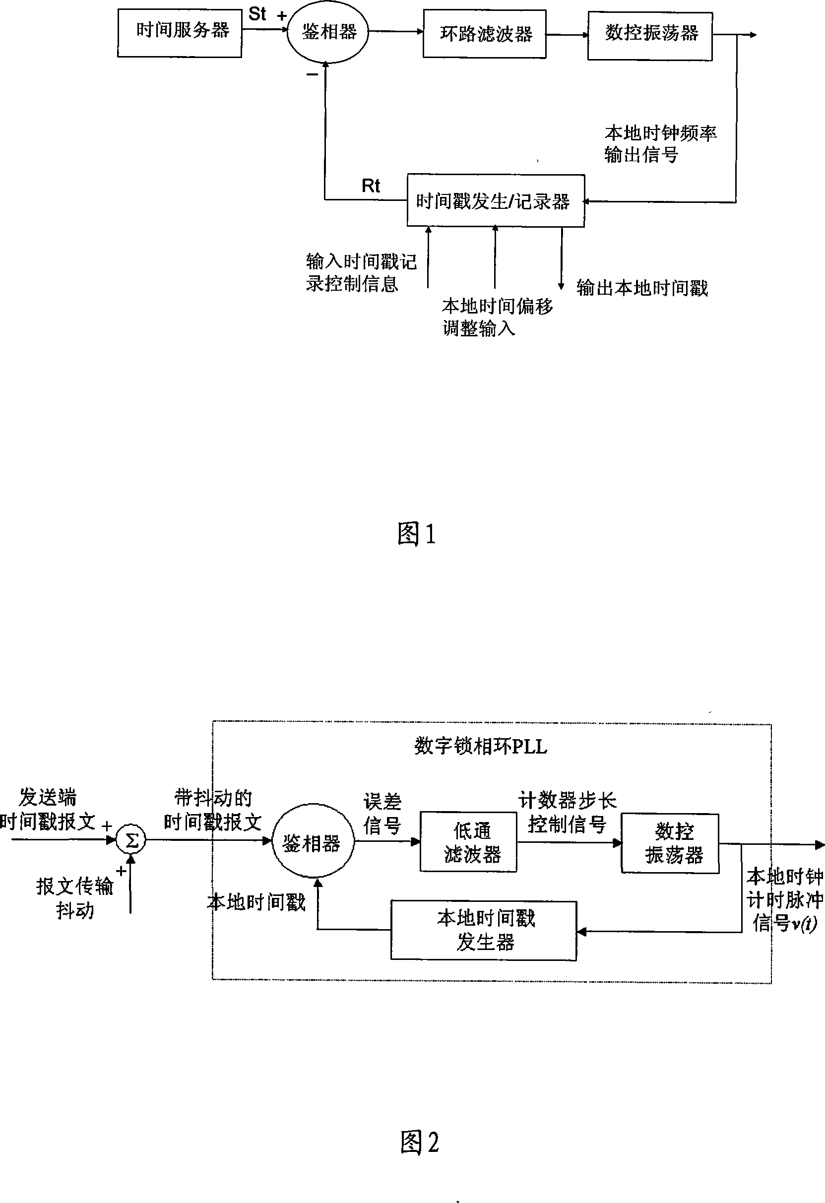
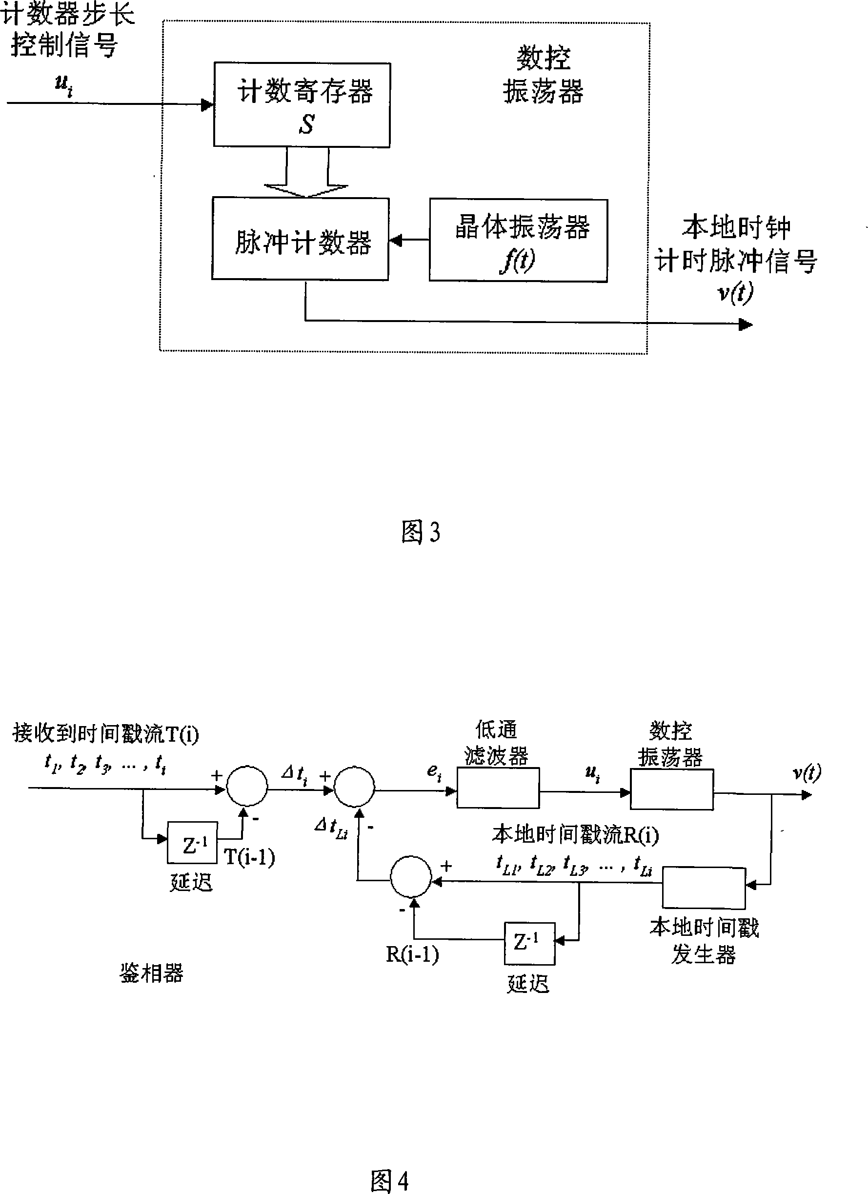
[0024] The structure of a specific embodiment of the present invention is shown in FIG. 1 . The phase-locked loop uses the time value carried in the time stamp message stream S(t) sent by the time server as the input synchronization signal of the phase detector of the digital phase-locked loop, which is used to output the phase-locked loop as the reference frequency of the local clock timing pulse The value of the local time stamp is the reference input signal of the phase detector. The acquired time of each local time stamp R(t) corresponds to the local clock time when a time stamp message sent from the time server arrives at the node where the PLL is located. The phase detector used is actually an integrated time stamp difference calculation / memory. It is mainly: calculate the difference between the timestamp values ​​carried by the timestamp messages sent by the time server before and after arriving at the phase detector respectively; calculate the value recorded when the ...


PUM


Abstract

The invention involves a method of digital phase-locked loop for timestamp clock synchronization and equipment. Firstly, the server sends a value, which includes the message S (t) to timestamp, as the input synchronized signal. Take the time on which timestamp the server sent arriving at phase-locked loop as the recording time R (t) of local time. Then take the local timestamp according to the local clock frequency as reference input signal. The numerically controlled adjusts the output frequency according to ring circuit signal by filter. Lastly, the timestamp creater / recorder output the signal as the local clock frequency according to the output signal created by DOC. Under the condition that the invention use larger drift mobility and the lower stability oscillator, the system can provide high accuracy time synchronism.

Description

technical field [0001] The present invention relates to a method and device for realizing integrated time stamp clock synchronous phase-locked loop, in particular to a method and device for realizing time-synchronized digital phase-locked loop on distributed systems such as computer network, industrial measurement and control system and sensor network. device. Background technique [0002] With the increasing application of distributed systems, and in order to obtain better system performance, in high-speed wireless networks, wireless sensor networks and Ethernet, many applications have required time synchronization accuracy of 10μs or higher. Although it is theoretically possible to adopt a probabilistic time synchronization algorithm, use the client-server model to repeatedly read the reference time, and finally make the time synchronization of the system reach a certain accuracy, but in practical applications, the expansion of the system scale will be difficult. It is co...

Claims


Application Information

Patent Timeline
Patent Type & Authority Applications(China)
IPC IPC(8): H04L7/033H03L7/08H03L7/06
Inventor 刘桂雄全渝娟洪晓斌黄国健
Owner SOUTH CHINA UNIV OF TECH
Learn More