Phase-locked loop circuits and methods implementing pulsewidth modulation for fine tuning control of digitally controlled oscillators

a phase-locked loop and digital control technology, applied in the direction of pulse automatic control, angle demodulation by phase difference detection, electrical equipment, etc., can solve the problem of not being able to achieve a good analog pll circuit performance, not being able to achieve a pll with a low-noise output, and not being able to achieve the required fine-grain digital tuning of the lc dco using this approach, etc. problem, to achieve the effect of wide continuous

Inactive Publication Date: 2010-01-21
GLOBALFOUNDRIES INC
View PDF9 Cites 36 Cited by
  • Summary
  • Abstract
  • Description
  • Claims
  • Application Information

AI Technical Summary

Benefits of technology

[0015]In accordance with exemplary embodiments of the invention, rather than applying the dithered control signals to tuning controlled element in the DCO (e.g. capacitor in the LC DCO or inverter in the ring DCO) for a full clock cycle as in conventional schemes, pulse width modulation is applied to the dithered control signals so that the dithering control inputs are applied ...

Problems solved by technology

In advanced semiconductor technologies, the ability to realize good analog PLL circuit performance is problematic, especially as target supply voltages are reduced and operating frequencies increase.
If the frequency step between adjacent digital control settings is too large, however, it will not be possible to realize a PLL with a low-noise output.
However, the ability to achieve the required fine-grain digital tuning of the LC DCO using this approach can be problematic because there are inherent ...

Method used


Image

  • Phase-locked loop circuits and methods implementing pulsewidth modulation for fine tuning control of digitally controlled oscillators
  • Phase-locked loop circuits and methods implementing pulsewidth modulation for fine tuning control of digitally controlled oscillators
  • Phase-locked loop circuits and methods implementing pulsewidth modulation for fine tuning control of digitally controlled oscillators

Examples


Embodiment Construction

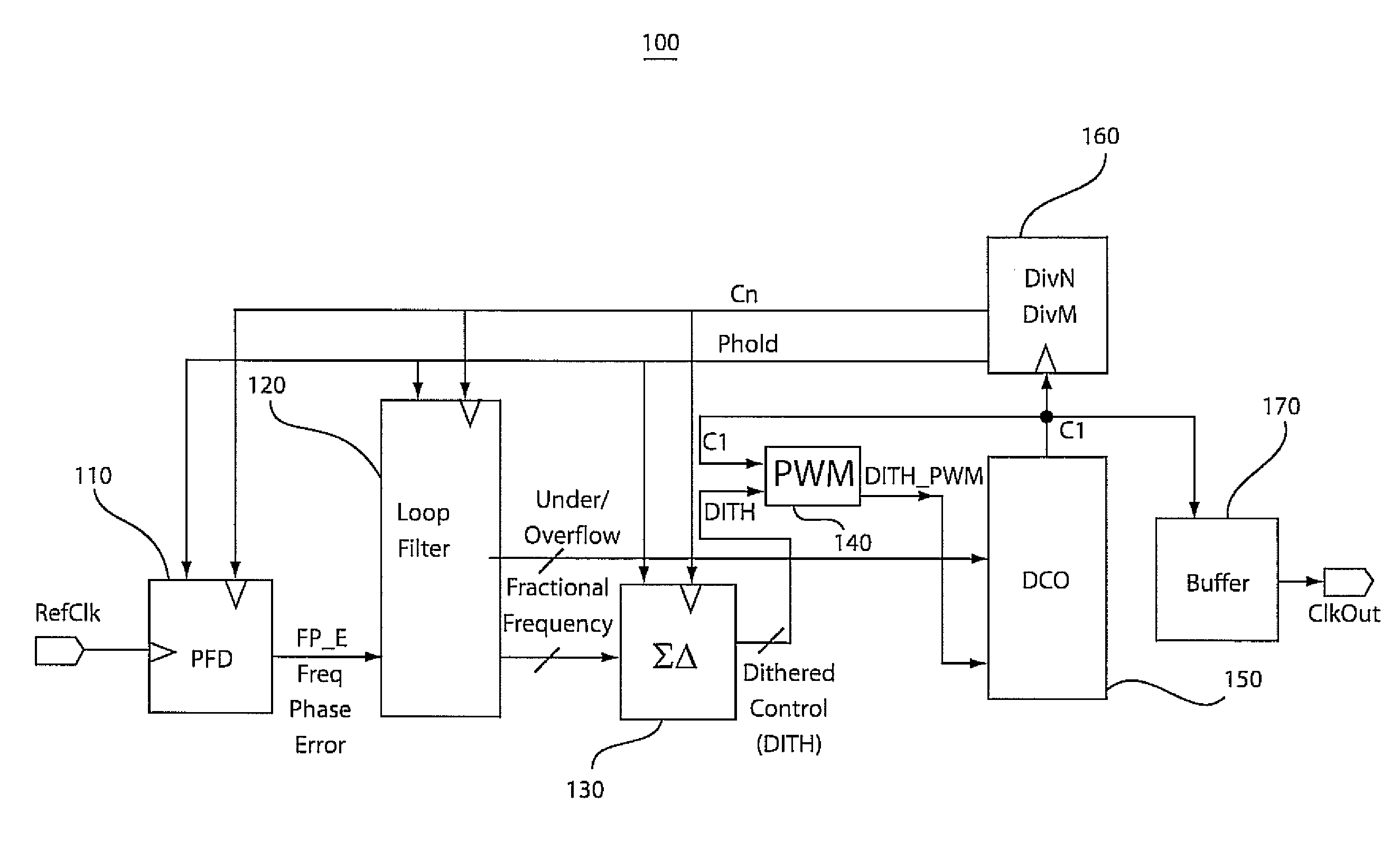
[0026]FIG. 1 is a schematic block diagram of a digital phase locked loop (DPLL) circuit (100) according to an exemplary embodiment of the invention. The DPLL (100) comprises a phase / frequency detector (110) (or “PFD” circuit), a digital loop filter (120), a sigma / delta modulator (130) (or “SDM” circuit), a pulse width modulator (140) (or “PWM” circuit), a digitally controlled oscillator (150) (or “DCO” circuit), a frequency divider (160), and an output buffer (driver) (170). In general, the PFD (110) compares the reference clock REF_Clock and divided clock CN and generates frequency / phase error (FP_E) signal. The loop filter (120) filters the FP_E signal to generate a DCO tuning control signal for the DCO (150). The control signal output from the loop filter (120) is divided into most significant bits (under / overflow control bits) that are directly input to the DCO (150) and least significant bits (fractional frequency control bits) that are input to the SDM (130). The SDM (130) mod...


PUM


Abstract

PLL (phase locked loop) circuits and methods are provided in which PWM (pulse width modulation) techniques are to achieve continuous fine tuning control of DCO (digitally controlled oscillator) circuits. In general, pulse width modulation techniques are applied to further modulate dithered control signals that are used to enhance the frequency tuning resolution of the DCO such that the dithered control signals are applied to the fractional tracking control port of the DCO for a selected fraction of a full clock signal based pulse width modulation applied.

Description

TECHNICAL FIELD OF THE INVENTION[0001]The present invention relates generally to PLL (phase locked loop) circuits and methods and, in particular, digital PLL circuits and methods implementing PWM (pulse width modulation) to achieve continuous fine tuning control of DCO (digitally controlled oscillator) circuits.BACKGROUND[0002]In general, various types of communications systems are implemented using phase-locked loop (PLL) circuits to generate clock signals. For example, PLL circuits are used in transceiver circuits for generating LO (local oscillator) signals, data recovery circuits for generating clock recovery signals, and frequency synthesizer circuits for generating stable frequency output signals over a large continuous tuning range. In general, a PLL circuit uses feedback to maintain an output signal of the PLL in a specific phase relationship with a reference input signal of the PLL, as is well known in the art. When the output frequency of the PLL is equal to the frequency ...

Claims


Application Information

Patent Timeline
IPC IPC(8): H03L7/06
CPCH03L7/093H03L2207/50H03L7/1075H03L7/107
Inventor AINSPAN, HERSCHEL A.FRIEDMAN, DANIEL J.RYLYAKOV, ALEXANDER V.TIERNO, JOSE A.
Owner GLOBALFOUNDRIES INC
Why Eureka
Try Eureka