Method for reducing the inrush current of an inductive load

a technology of inductive load and inrush current, which is applied in the direction of electric variable regulation, emergency protective arrangements for limiting excess voltage/current, instruments, etc., can solve the problems of inapplicability to high voltage, permanent connection of transformer, and harm to the machine and to the mains or electrical power lines. , to achieve the effect of reducing the inrush curren

Active Publication Date: 2017-05-11
INDRA SISTEMAS
View PDF5 Cites 6 Cited by
  • Summary
  • Abstract
  • Description
  • Claims
  • Application Information

AI Technical Summary

Benefits of technology

[0020]The invention provides a method for reducing the inrush current of an

Problems solved by technology

One of the usual problems when starting an electric machine is that the inrush current is much higher than the rated current, which can be harmful to the machine and to the mains or electrical power lines.
The problems caused by these high current values on the physical structure of the transformer are well known, and go up to the point to decide not to deenergize the transformer to avoid the stress caused when it is energized again, which causes the situation that the transformer is permanently connected to the mains.
H

Method used


Image

  • Method for reducing the inrush current of an inductive load
  • Method for reducing the inrush current of an inductive load
  • Method for reducing the inrush current of an inductive load

Examples


Embodiment Construction

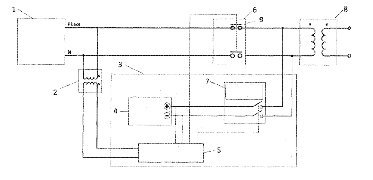
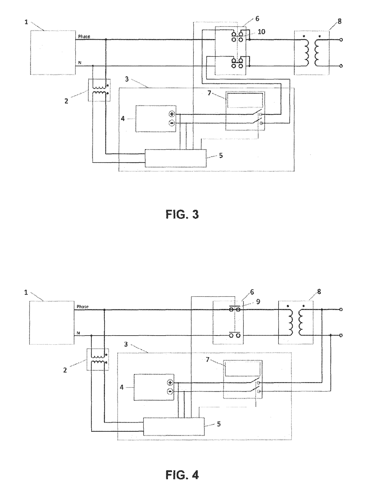
[0038]References of the figures correspond to the following elements:

[0039]1.—One-phase power input.

[0040]2.—Measuring transformer.

[0041]3.—Control system for one-phase transformer.

[0042]4.—DC power supply.

[0043]5.—Phase Controller.

[0044]6.—Power switch.

[0045]7.—DC switching.

[0046]8.—One-phase transformer.

[0047]9.—Standard power circuit breaker.

[0048]10.—Two circuit power circuit breaker.

[0049]12.—Three-phase power input.

[0050]13.—Phase A power circuit breaker.

[0051]14.—Phase B power circuit breaker.

[0052]15.—Phase C power circuit breaker.

[0053]16.—Three-phase transformer with primary winding wye connected.

[0054]17.—Control system for three-phase transformer.

[0055]18.—Three-phase transformer with primary winding delta connected.

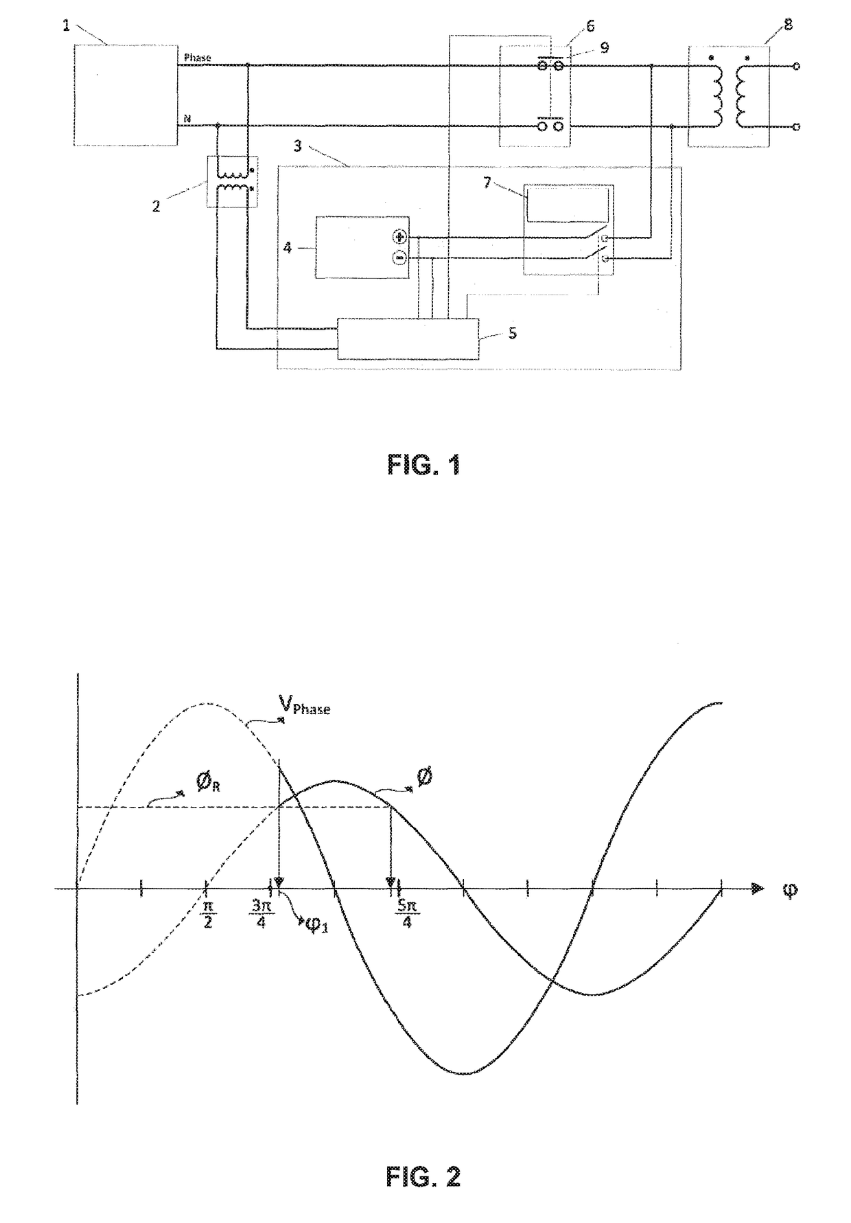
[0056]FIG. 1 shows the wiring diagram and the control system to power a one-phase transformer 8 suppressing the inrush current

[0057]Control system 3 requires having a sample of the input voltage, accessing to the activation solenoid of the circuit breaker 6 a...


PUM


Abstract

A method for reducing the inrush current of an inductive load, particularly a transformer, comprising the following steps: a) connecting a DC power source to the transformer for a time tc, to magnetize its magnetic core until saturation is reached, and connecting the transformer to the AC mains via an electromechanical switch, in an initially open position; b) disconnecting the transformer from the DC power source, the magnetic flux being reduced to its residual value; c) closing the electromechanical switch to complete the connection, this connection point being determined by the phase angle selected from the sinusoidal signal of the voltage power lines, in such a way that magnetic flux corresponding to the steady state voltage equals the residual magnetic flux that remains when the transformer is disconnected from the DC power source.

Description

FIELD OF THE INVENTION[0001]The present invention relates to a method for reducing the inrush current of inductive loads, and is especially applicable to suppress inrush current when connecting transformersBACKGROUND OF THE INVENTION[0002]One of the usual problems when starting an electric machine is that the inrush current is much higher than the rated current, which can be harmful to the machine and to the mains or electrical power lines.[0003]In the specific case of connection of transformers, when a transformer is powered on, transient currents can appear with values up to several times the transformer's rated current. The duration and intensity of this current is determined by constructive aspects of the transformer, the line resistance and mainly the residual flux of the transformer and the connection instant.[0004]Depending on the instant the power supply is applied to the transformer, the magnetic flux wave can reach a peak value higher than twice its maximum value in normal...

Claims


Application Information

Patent Timeline
IPC IPC(8): H02H9/00G05F5/00H02H9/02
CPCH02H9/002G05F5/00H02H9/021
Inventor FOTROUSI, FARZAD
Owner INDRA SISTEMAS
Why Eureka
Try Eureka