
Optical imaging method using single pixel detector

a detector and optical imaging technology, applied in the field of optical imaging, can solve the problems of reducing the signal-to-noise ratio, reducing the number of measurements, and the difficulty of spectral characteristics of photosensitive devices for imaging applications beyond visible waveband, so as to achieve high-quality reconstructed images and reduce the number of measurements.

Active Publication Date: 2017-05-11
JINAN UNIVERSITY
View PDF2 Cites 25 Cited by
  • Summary
  • Abstract
  • Description
  • Claims
  • Application Information

AI Technical Summary

Benefits of technology

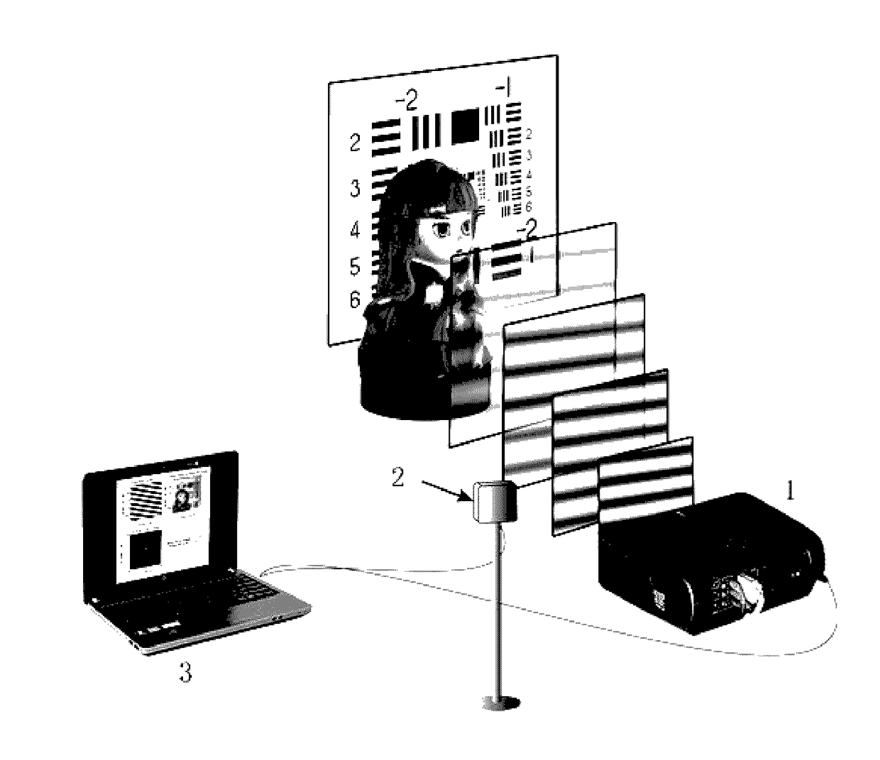
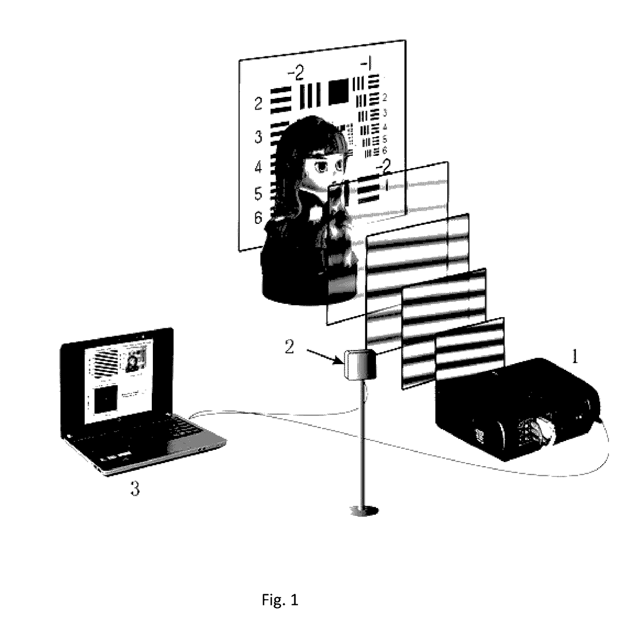
The present invention offers an optical imaging method using a single-pixel detector with high quality. It achieves this by using light fields with a cosine spatial structure that have a definite mathematical function analytical expression to replace speckle light field in thermal source ghost imaging technology. An image analytical reconstruction algorithm is established on the basis of the light fields, which allows for a significantly reduced number of measurements and obtains a high-quality reconstructed image. Compared with prior art, the present invention offers improved imaging quality and efficiency.

Problems solved by technology

However, photosensitive devices with small pixel pitch are commonly difficult to be manufactured and might reduce signal-to-noise ratio.
Besides, the spectral characteristics of photosensitive device have larger difficulty for some imaging applications beyond visible waveband.
For example, the existing CCD, CMOS and other imaging devices based on silicon-based semiconductor have difficulty in working over bands like infrared, terahertz, X-ray, and etc.
In the conventional imaging model, only the light that is from target object and transmits through lenses without scattering in transmission from the object to the detector keeps the spatial information of the target object and with such light the image can be formed; however, the light that is scattered in transmission losses the spatial information of the target object has no contribution to imaging but to noise.
Therefore, it is challenging to image a target object hidden behind any scattering media (such as, ground glass) by means of the conventional imaging.
However, the imaging quality of single-pixel imaging techniques is hardly comparable to that of existing conventional optical imaging techniques.
Such a probabilistic nature also leads to the facts that a great number (millions) of measurements are needed to reconstruct an image, and that the reconstruction result is only an approximation to the true one and the reconstruction quality is not comparable to that by conventional optical imaging techniques.

Method used


Image

  • Optical  imaging method  using  single  pixel detector
  • Optical  imaging method  using  single  pixel detector
  • Optical  imaging method  using  single  pixel detector

Examples


embodiment 1

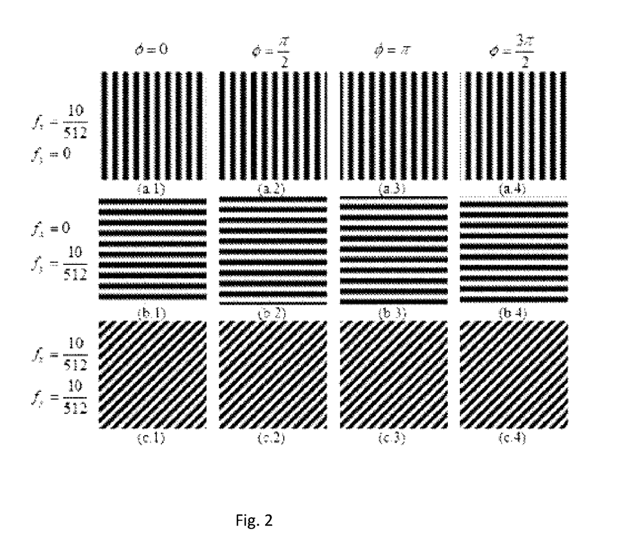
[0024]The image of the target object under structured light illumination is expressed by using a matrix of M×N pixels. The actual size of the scene consisting of the target object is in the shape of a rectangle whose size is Mδx×Nδy, M and N are positive integers, and δx×δy is a geometrical dimension of one pixel. The Fourier spectrum of the image of the target object is also discretized into a matrix of M×N pixels. The spatial frequencies fx and fy corresponding to each matrix element are respectively normalized to

αMandβN,

where α is an integer number between 0˜M−1, and β is an integer number between 0˜N−1. A digital projector is used as a structured light field generator. The computer controls the digital projector to generate the light fields. Each spatial frequency pair corresponds to four light fields with different initial phases (0, π / 2, π and 3π / 2). The light fields are illuminated onto the target object sequentially.

[0025]A single-pixel detector is used for imaging of a comp...


PUM


Abstract

An optical imaging method using a single-pixel detector. An image of a target object is expressed by using discrete pixels, and the size of the image is M×N pixels. A cosine structured light field generator is used for generating a series of light fields that have different frequencies and are distributed according to cosine, wherein each set of frequencies corresponds to at least three different initial phase φ values; the light fields with cosine distribution that have different frequencies and different initial phases are used to sequentially irradiate the target object; an optical detector (2) is used for sequentially receiving light intensity signals from the target object and then response values of the optical detector (2) are sequentially collected and recorded; An image reconstruction algorithm is established on the basis of the light fields, the number of measurements can be greatly reduced, and a high-quality reconstructed image can be obtained.

Description

TECHNICAL FIELD[0001]The present invention relates to the technical field of optical imaging, and more specifically, to an optical imaging method using single-pixel detector.BACKGROUND OF THE INVENTION[0002]Image is human's primary information source, and optical imaging is the primary way to obtain images. An optical imaging system generally consists of an illumination unit and a detection unit. Performing optical imaging on a non-luminous target object by the conventional way is generally to illuminate the object with a stable and uniform illumination light field, and to collect the light reflected from the object surface through some lenses so as to form an image of the target object onto some photosensitive recording medium (such as photographic film, pixelated CCD camera, pixelated CMOS camera, and etc.). The performances of the utilized lens and photosensitive device are main factors to affect imaging quality. The resolution of the resultant images is subject to the pixel pitc...

Claims


Application Information

Patent Timeline
Patent Type & Authority Applications(United States)
IPC IPC(8): H04N5/369G01B11/25
CPCG01B11/25H04N5/369G01B11/2513G06T1/0007H03M7/3062H04N23/56H04N25/00
Inventor ZHONG, JINGANGZHANG, ZIBANGMA, XIAO
Owner JINAN UNIVERSITY
Learn More