Milling device and method for milling within a slot

a milling device and slot technology, applied in the field of milling devices, can solve the problems of reducing affecting the service life of the turbine rotor, and being subjected to very high mechanical and also chemical loads, and achieve the effect of reliable calculation of the remaining service life and/or the expected crack growth

Inactive Publication Date: 2017-05-18
SIEMENS ENERGY GLOBAL GMBH & CO KG
View PDF14 Cites 0 Cited by
  • Summary
  • Abstract
  • Description
  • Claims
  • Application Information

AI Technical Summary

Benefits of technology

[0006]An aspect relates to a milling device of the type mentioned in the introduction, and a method for milling within a slot of a component using such a milling device, which permits reliable calculation of the remaining service life and / or of the expected crack growth.
[0007]A further aspect provides a milling device of the type mentioned in the introduction, which is characterized in that it has a slide, and in that the milling tool is held on a pivot axis that extends transversely, in particular perpendicular, to the tool rotation axis and through the slide, wherein the slide is designed and the position of the milling tool is selected such that, during milling, a traversing movement is effected by manually moving the slide and advance is effected by pivoting the milling tool about the pivot axis. If the shape of the slide is matched, for example to the shape of a slot that is to be machined, in the manner of a template, the slide permits exact guiding of the milling tool along the direction of extent of the slot, thus achieving a defined movement of the milling tool during milling. The slide also makes it possible to perform milling at hard-to-reach points within the slot. In that context, the pivot position of the milling tool can be used to set a defined advance. In all, the milling device according to embodiments of the invention thus permits the creation of defined and axially constant machining contours when determining the depth of a crack or when grinding out a crack, to name just some possible exemplary uses. After machining of cracks, the defined machining contours also make it possible to carry out further calculations with reliable results, such as in particular calculations for determining the remaining service life of the component or the expected crack growth.
[0008]According to one embodiment of the present invention, the slide is made of plastic. Plastic is advantageous on one hand because it is easily worked to produce the slide. Also, the slide can readily be produced by using a rapid prototyping method. In particular, use is made of a plastic with good sliding properties in order to thus facilitate manual moving of the slide along a component.

Problems solved by technology

Turbine rotor blades and blade root receiving slots, which are formed on the rotor and in which the turbine rotor blades are held, are subjected to very high mechanical and also chemical loads during operation of the turbine.
This causes, inter alia, crack formation within the blade root receiving slots, which can greatly reduce the service life of the turbine rotor.
If this is inadequate, suitable countermeasures must be taken.
However, an important drawback of this approach is that the milling is performed manually.
Accordingly, the milling does not create defined and / or axially constant machining contours, making it difficult to reliably calculate the remaining service life and / or the expected crack growth.

Method used


Image

  • Milling device and method for milling within a slot
  • Milling device and method for milling within a slot
  • Milling device and method for milling within a slot

Examples


Embodiment Construction

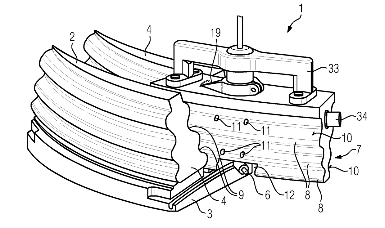
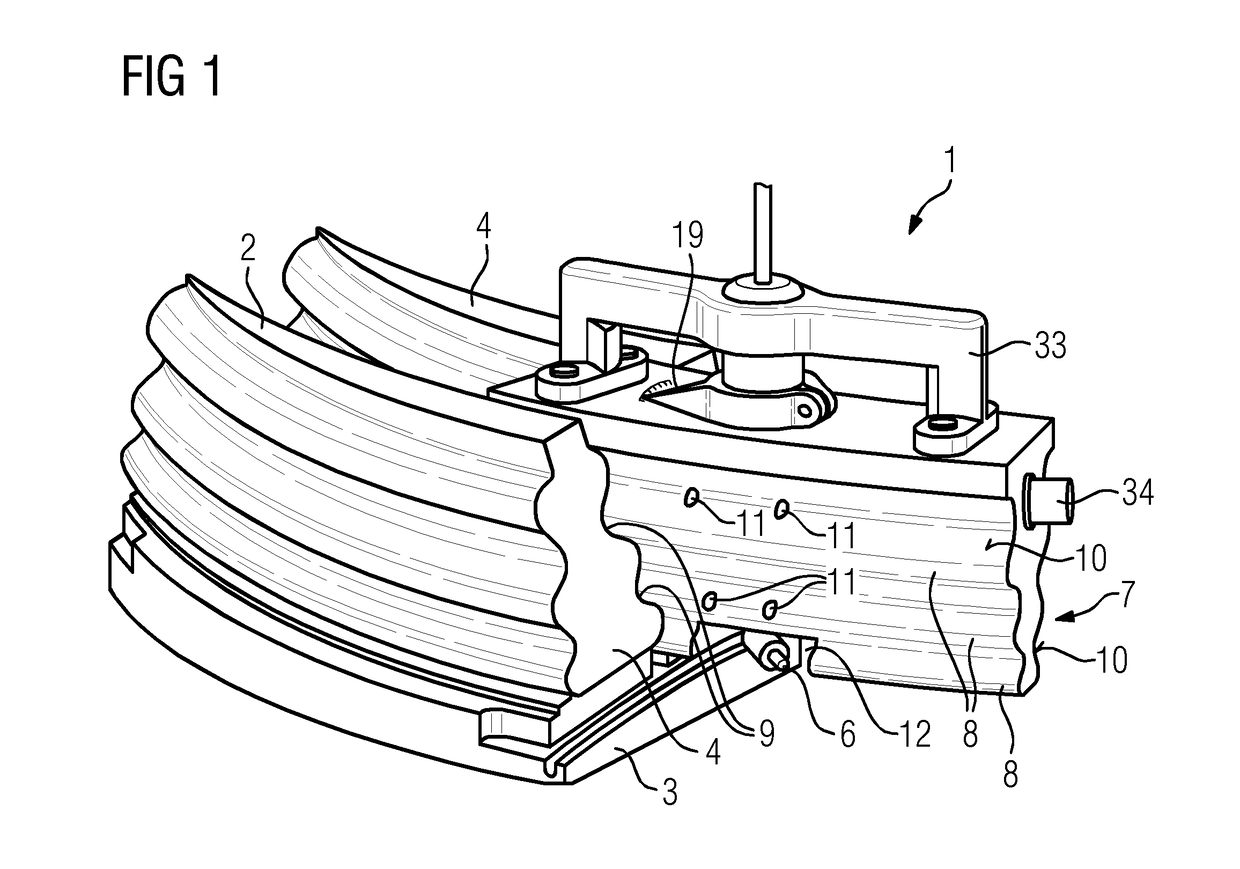
[0027]The Figures show a milling device 1, according to one embodiment of the present invention, which is configured for milling within a blade root receiving slot 2 of a rotor 3 (only partially shown in FIG. 1) of a turbomachine, in which one sidewall of a rotor steeple 4 that defines the blade root receiving slot 2 is machined in a chip-removing manner. The blade root receiving slots 2 of the rotor 3 are identical and have, in the present case, a constant fir-tree cross section along their longitudinal extent.

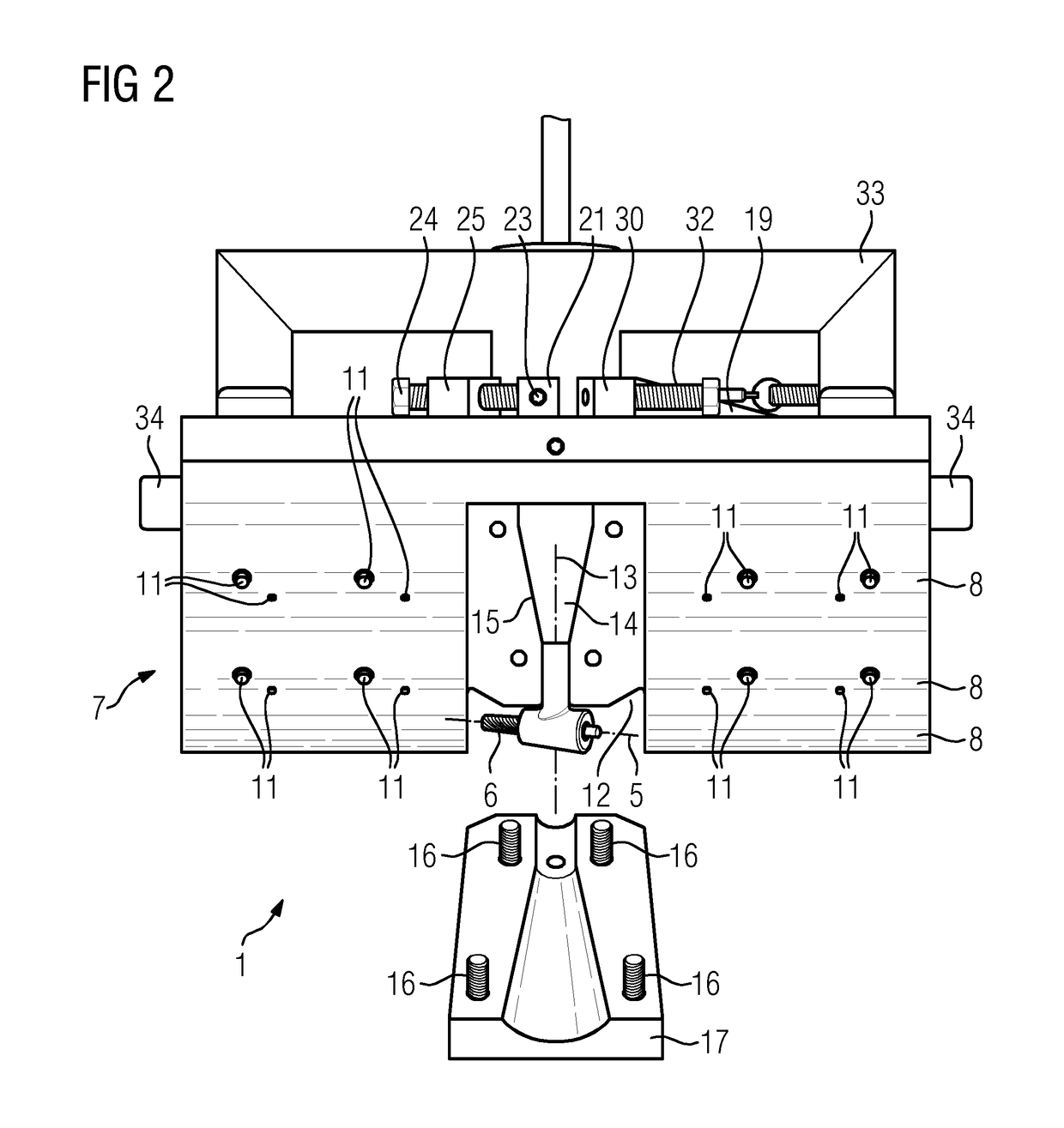
[0028]The milling device 1 comprises, as principal components, a milling tool 6 (in the present case a finger-type milling cutter) that rotates about a tool rotation axis 5, and a slide 7 holding the milling tool 6.

[0029]The slide 7 is elongate, and its cross section, which matches the fir-tree cross section of the blade root receiving slots 2, is essentially constant over its longitudinal extent. Accordingly, the slide 7 can be introduced into a blade root receiving slot 2 a...


PUM

PropertyMeasurementUnit
spring forceaaaaaaaaaa
pressureaaaaaaaaaa
shapeaaaaaaaaaa

Abstract

A milling device is provided, having a milling tool that rotates about a tool rotation axis, wherein the milling device has a slide, and in that the milling tool is held on a pivot axis that extends transversely, in particular perpendicular, to the tool rotation axis and through the slide, wherein the slide is designed and the position of the milling tool is selected such that, during milling, a traversing movement is effected by manually moving the slide and advance is effected by pivoting the milling tool about the pivot axis. Also provided is a method for milling within a slot of a component, in particular within a blade root receiving slot of a turbomachine, using a milling device.

Description

CROSS-REFERENCE TO RELATED APPLICATIONS[0001]This application claims priority German Application No. 102015222529.1 having a filing date of Nov. 16, 2015, the entire contents of which are hereby incorporated by reference.FIELD OF TECHNOLOGY[0002]The following relates to a milling device having a milling tool that rotates about a tool rotation axis. The following also relates to a method for milling within a slot, in particular, within a blade root receiving slot of a turbomachine, using such a milling device.BACKGROUND[0003]Turbine rotor blades and blade root receiving slots, which are formed on the rotor and in which the turbine rotor blades are held, are subjected to very high mechanical and also chemical loads during operation of the turbine. This causes, inter alia, crack formation within the blade root receiving slots, which can greatly reduce the service life of the turbine rotor. Within the context of maintenance and repair work, crack findings are recorded accordingly, and t...

Claims


Application Information

Patent Timeline
Patent Type & Authority Applications(United States)
IPC IPC(8): B23C3/34B23Q9/00
CPCB23C3/34B23C2220/366B23C2215/52B23Q9/0007B23C3/00B23C3/28B23C3/30B23P6/002B23Q9/02B23Q9/0014Y10T409/306384F01D5/005
Inventor CLOSSEN-VON LANKEN SCHULZ, MICHAELOBERMAYR, STEFAN
Owner SIEMENS ENERGY GLOBAL GMBH & CO KG
Why Eureka
Try Eureka