Hybrid vehicle

a hybrid vehicle and hybrid technology, applied in the direction of engine-driven generators, electric devices, transportation and packaging, etc., can solve the problems of insufficient output of plug-in hybrid vehicles, inconvenient waiting for a certain time, etc., to prevent occurrence, and reliably output the required output

Inactive Publication Date: 2017-05-18
TOYOTA JIDOSHA KK
View PDF0 Cites 4 Cited by
  • Summary
  • Abstract
  • Description
  • Claims
  • Application Information

AI Technical Summary

Benefits of technology

[0012]In the above hybrid vehicle according to the present disclosure, the electronic control unit may be configured to cause the drive mode to shift into the hybrid drive mode, when the predetermined high response request is being issued in the charge sustaining mode in the electric drive mode, and when the required output becomes larger than a second threshold larger than the first threshold. Generally, a maximum output outputtable to the drive shaft in the hybrid drive mode is larger than a maximum output outputtable to the drive shaft in the double-drive mode. Therefore, as in the case of the hybrid vehicle, when the predetermined high response request is being issued in the CS mode in the electric drive mode, and when the required output becomes larger than the second threshold, the drive mode is caused to shift into the hybrid drive mode. Thus, when the required output is larger than the second threshold, it is possible to further reliably output the required output to the drive shaft.
[0013]In the hybrid vehicle configured to cause the drive mode to shift into the hybrid drive mode when the required output becomes larger than the second threshold when the predetermined high response request is being issued in the CS mode in the electric drive mode, the second threshold may be a value larger than a maximum double-drive output that is a maximum output outputtable to the drive shaft in the double-drive mode. The electronic control unit may be configured to cause the drive mode to shift into the hybrid drive mode even when the required output is not larger than the second threshold, when the required output is larger than the first threshold and the predetermined high response request is being

Problems solved by technology

When the hybrid vehicle shifts from the EV drive mode to the HV drive mode, the hybrid vehicle is required to start the engine, so it is inconvenient that it takes a certain time until the engine functions as a power source.
In the CS mode, even when a high response req

Method used


Image

  • Hybrid vehicle
  • Hybrid vehicle
  • Hybrid vehicle

Examples


Embodiment Construction

[0028]Embodiments of the present disclosure will be described.

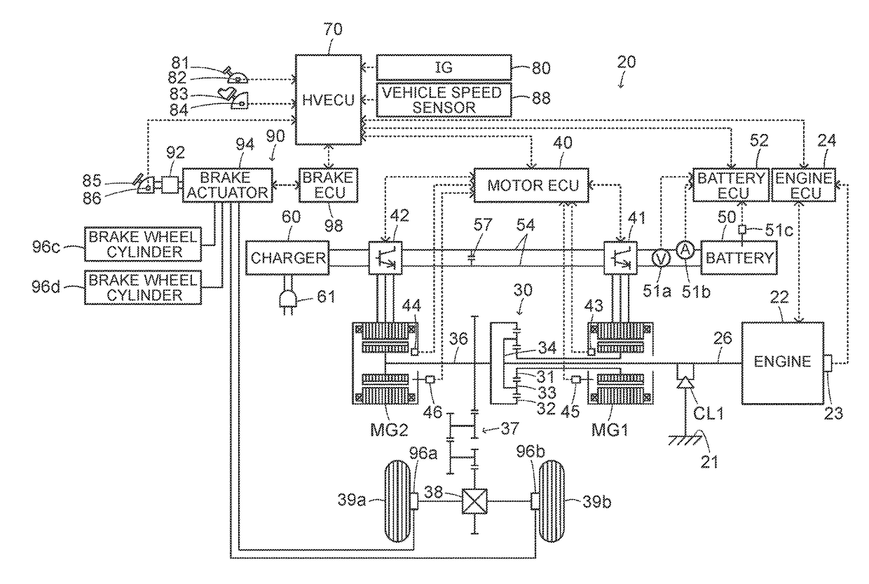
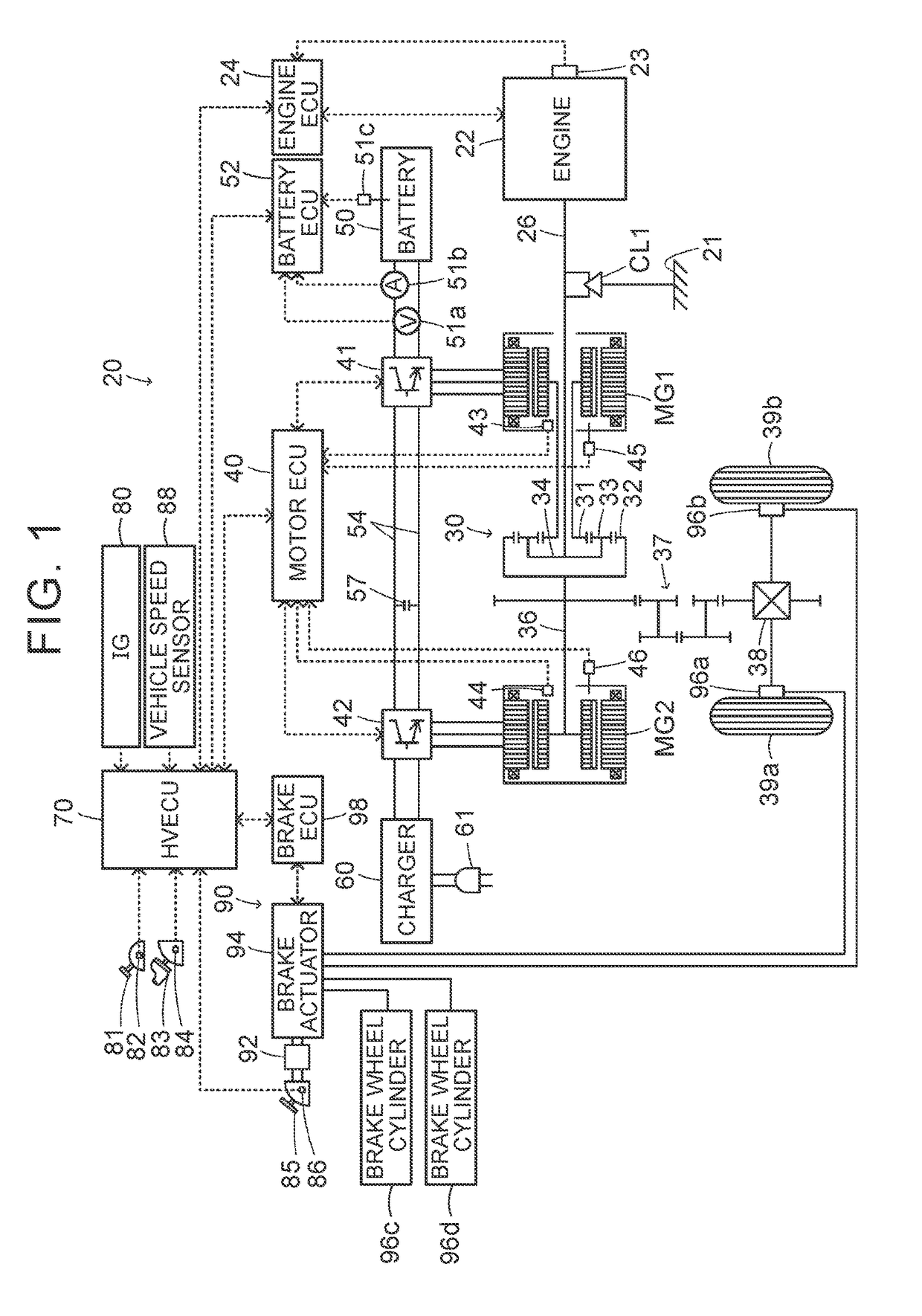
[0029]FIG. 1 is a configuration view that schematically shows the configuration of a hybrid vehicle 20 according to a first embodiment of the present disclosure. As shown in FIG. 1, the hybrid vehicle 20 according to the first embodiment includes an engine 22, a planetary gear 30 that serves as a planetary gear set, a one-way clutch CL1, motors MG1, MG2, inverters 41, 42, a battery 50, a charger 60, a hydraulic brake device 90 and a hybrid electronic control unit (hereinafter, referred to as HV-ECU) 70.

[0030]The engine 22 is configured as an internal combustion engine that outputs power by using gasoline, light oil, or the like, as fuel. The engine 22 undergoes operation control that is executed by an engine electronic control unit (hereinafter, referred to as engine ECU) 24.

[0031]Although not shown in the drawing, the engine ECU 24 is a microprocessor that mainly includes a CPU and that further includes a ROM, a RAM, inp...


PUM


Abstract

When a hybrid vehicle travels in CS mode in EV single-drive mode, when a required torque is larger than a torque threshold or when a required power is larger than a power threshold, and when a predetermined high response request is not being issued, a drive mode is caused to shift into HV drive mode. When the predetermined high response request is being issued, the drive mode is caused to shift into EV double-drive mode.

Description

CROSS-REFERENCE TO RELATED APPLICATIONS[0001]This application claims priority to Japanese Patent Application No. 2015-222054 filed on Nov. 12, 2015, the entire contents of which are hereby incorporated by reference.BACKGROUND[0002]1. Technical Field[0003]The present disclosure relates to a hybrid vehicle.[0004]2. Description of Related Art[0005]Conventionally, there is suggested a hybrid vehicle (see, for example, Japanese Patent Application Publication No. 2013-147193 (JP 2013-147193 A). In this hybrid vehicle, a first rotary electric machine is connected to a sun gear of a planetary gear, an engine is connected to a carrier, a drive shaft is connected to a ring gear, a second rotary electric machine is connected to the drive shaft, a one-way clutch is connected to the carrier and a battery is electrically connected to the first rotary electric machine and the second rotary electric machine. The hybrid vehicle selectively travels in EV drive mode or HV drive mode in charge depletin...

Claims


Application Information

Patent Timeline
IPC IPC(8): B60W20/10B60K6/365B60W30/18B60L15/00B60K6/445B60K6/28B60K6/383B60L50/16
CPCB60W20/10B60K6/28B60K6/365B60K6/383B60L15/007B60W2550/148B60W30/18172Y10S903/91Y10S903/93B60Y2200/92B60K6/445B60K6/44B60W10/06B60W10/08B60W20/20B60W20/40B60W2510/081B60W2520/10B60W2540/10B60W2710/0666B60W2710/083B60L3/10B60L2240/465B60L2240/647B60W2510/244B60W2540/103B60W2552/40Y02T10/62Y02T10/72Y02T90/16
Inventor SATO, KEITA
Owner TOYOTA JIDOSHA KK
Why Eureka
Try Eureka