Multifunction thruster assembly for watercraft

a multi-functional, watercraft technology, applied in the field of thrusters, can solve the problems of increasing energy consumption, consuming a degree of power, and generally tight power budgets

Active Publication Date: 2017-05-18
OCEAN AERO
View PDF5 Cites 6 Cited by
  • Summary
  • Abstract
  • Description
  • Claims
  • Application Information

AI Technical Summary

Benefits of technology

[0011]The passage into the vessel may comprise a chamber having the opening of the passage formed therein. The passage may further comprise at least one conduit extending from the chamber to an interior of the vessel. The at least one conduit may comprise an input conduit through which water flows from the chamber to on board the vessel in response to operation of the thruster in a first direction. The at least one conduit may comprise an outlet conduit through which water is withdrawn from the vessel in response to operation of the thruster in an opposite direction. The at least one conduit may comprise a first, inlet conduit in fluid communication with the chamber, and a second, outlet conduit in a fluid communication with the chamber. The conduits may comprise check valves that prevent backflow of water therethrough.

Problems solved by technology

Thruster units provide significant advantages in many applications, but like all propulsion systems they consume a degree of power.
Power consumption is virtually always a concern in vessel design and operation, but it even more so in the case of watercraft and other vessels that are small in size and / or are intended to operate for long periods of time without refueling.
The low energy density of environmental sources (wind, solar, wave) means that comparatively small amounts of power can be obtained, with the result that the power budget is generally very tight.
A related factor is that any added weight requires more power to propel, thus increasing energy consumption.
Furthermore, complexity and multiple components tend to both increase cost and reduce reliability, the latter again being a particularly significant consideration in the context of UAVs that must operate for extended periods with little or no human intervention.
Weight and complexity also negatively impact the ability to transport, launch / retrieve and handle the craft.
Furthermore, after arriving at the operating area the craft must frequently be handled and launched from / recovered to a ship or other mother vessel, where excess weight can be a significant detriment.
Still further, excess weight can compromise the vessel's maneuverability and responsiveness during operation.

Method used


Image

  • Multifunction thruster assembly for watercraft
  • Multifunction thruster assembly for watercraft
  • Multifunction thruster assembly for watercraft

Examples


Embodiment Construction

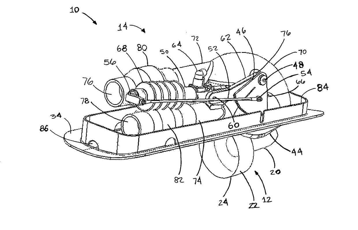
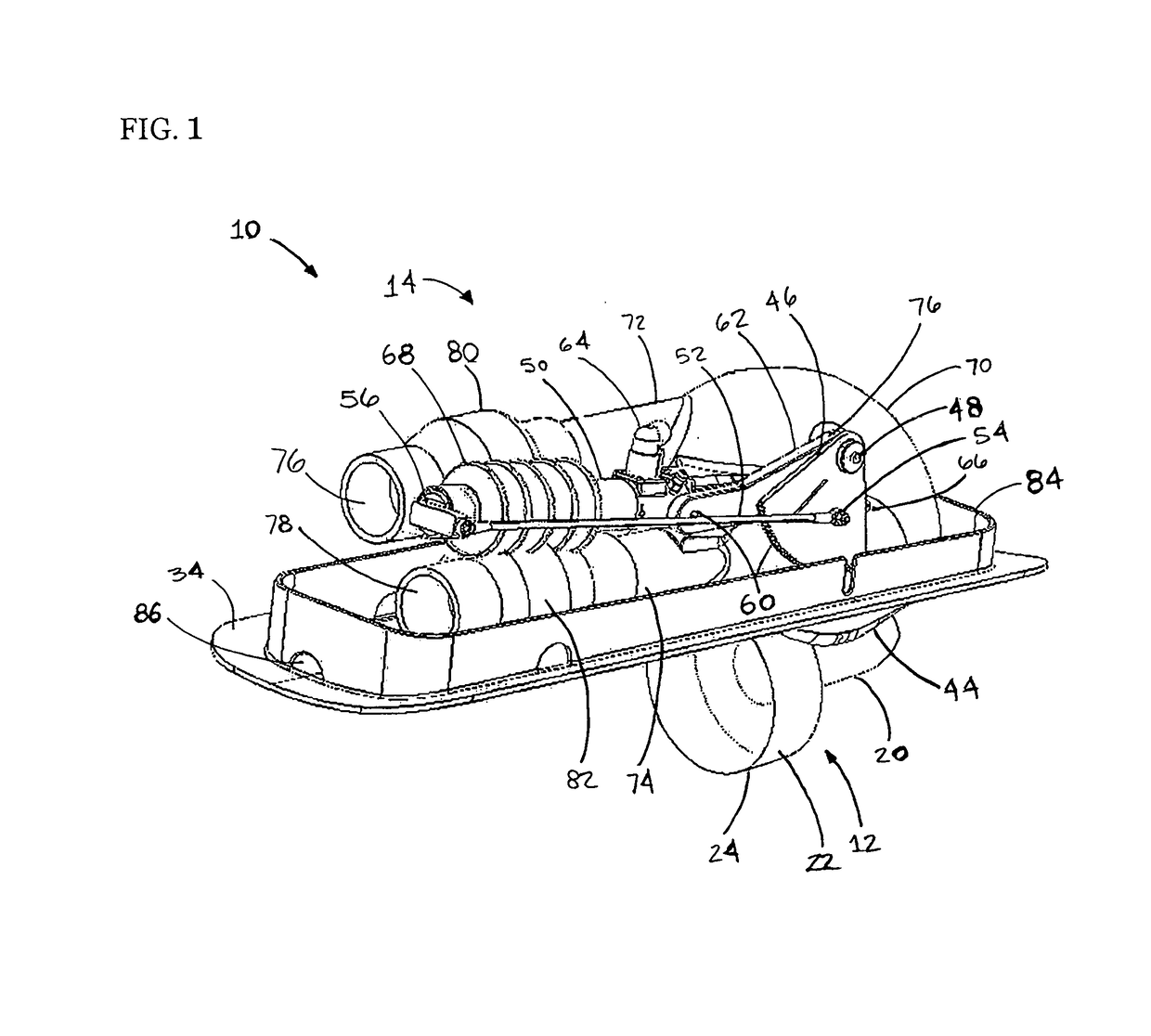
[0029]FIG. 1 shows a multifunction thruster assembly 10 in accordance with the present invention. Principal subassemblies of the system include a thruster assembly 12 and a flow directing assembly 14. As will be described in greater detail below, the thruster assembly includes a motor-driven thruster that generates a flow of water, while the flow directing system in turn positions the thruster and directs the flow to perform multiple tasks, namely, propulsion and ballasting of the vessel in the illustrated embodiment. It will be understood that, depending on application, additional secondary functions may be performed in addition to ballasting of the vessel, such as systems cooling or washdown functions, for example.

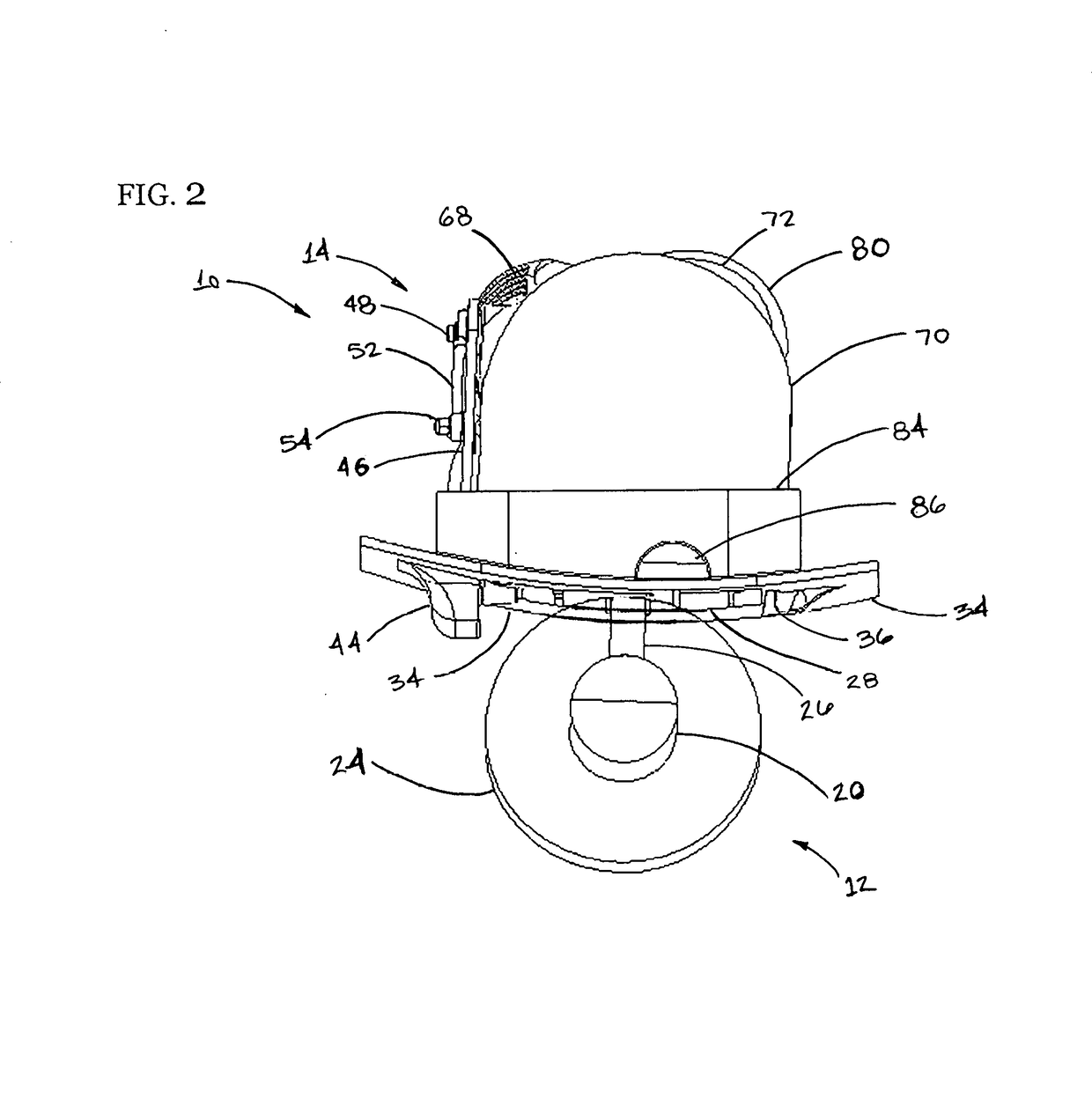
[0030]Referring again to FIG. 1 and also FIGS. 2-3, it can be seen that the thruster assembly 12 includes a motor section 20 having a drive motor, which may be an electric motor driven by batteries in the associated vessel, or which may be of a hydraulic, mechanical or o...


PUM


Abstract

A thruster assembly that in addition to propulsion provides water flow to / from compartments and systems on board a vessel. In a first position, the thruster assembly provides propulsion / steering. Pivoted to a second position, operation of the thruster in a first direction draws a flow into the vessel and in a second direction draws a flow out of the vessel. The flows may be conveyed to / from compartments / systems on board the vessel via conduits in communication with a chamber having an opening through which the thruster drives the flows. The flows may be used to submerge / surface the vessel, or to provide systems cooling or serve other functions. Pivoted to a third position the thruster assembly is retracted and enclosed within the chamber to form a hydrodynamically clean exterior.

Description

RELATED CASES[0001]This application claims the benefit of Provisional Patent Application Ser. No. 62 / 231,163 filed Jun. 25, 2015.BACKGROUND[0002]a. Field of the Invention[0003]The present invention relates generally to thrusters that provide motive power for watercraft, and, more particularly, to a thruster assembly that performs both propulsion and ballasting / dewatering functions onboard a vessel.[0004]b. Related Art[0005]Thrusters, as relate to waterborne vessels, are propulsive devices that are generally employed to propel and / or maneuver the vessel. As compared with shaft drives and other forms of propulsion that employ a remote power plant, thruster units commonly include an electric or hydraulic motor mounted in close association with the propeller itself in a submerged location, with electrical power or hydraulic pressure being supplied to the motor from a remote location within the hull. The propeller is frequently enclosed within a circular shroud. The motor may be reversib...

Claims


Application Information

Patent Timeline
Patent Type & Authority Applications(United States)
IPC IPC(8): B63H11/02B63B39/03B63G8/22B63H25/46B63G8/08
CPCB63H11/02B63H25/46B63G8/08B63B2751/00B63B39/03B63B2207/02B63G8/22B63B13/00B63B13/02B63H23/24B63G8/16B63H5/14B63B2035/007B63G2008/004B63H2005/075B63H2025/425
Inventor AYOTTE, THOMAS M.CLIFTON, SCOTT M.TODTER, CHRIS G.TODTER, MICHAEL M.
Owner OCEAN AERO
Why Eureka
Try Eureka