Translucent structure

a transparent structure and transparent technology, applied in the field of transparent structures, can solve the problems of increased antiglare property, reduced image visibility, and high haze, and achieve the effects of reducing haze, excellent antiglare property, and sufficiently suppressing the sparkle of the invention

Active Publication Date: 2017-05-18
ASAHI GLASS CO LTD
View PDF1 Cites 17 Cited by
  • Summary
  • Abstract
  • Description
  • Claims
  • Application Information

AI Technical Summary

Benefits of technology

[0030]The translucent structure of the present invention is excellent in the antiglare property, and sparkle of it is sufficiently suppressed.
[0031]According to the process for producing the translucent structure of the present invention, it is possible to produce a translucent structure which is excellent in the antiglare property and of which sparkle is sufficiently suppressed.
[0032]The translucent structure which the article of the present invention has is excellent in the antiglare property, and sparkle of it is sufficiently suppressed.

Problems solved by technology

However, at the same time, sparkle may occur on the surface of the antiglare film, whereby the image visibility decreases.
For example, in a case where an antiglare film is formed by a spray method, if the coating liquid is applied several times, the haze tends to be high and the antiglare property is increased, however, sparkle tends to be significant.
However, in Patent Document 2, the haze is at most 10%, and the antiglare property is insufficient.

Method used


Image

  • Translucent structure
  • Translucent structure
  • Translucent structure

Examples


first embodiment

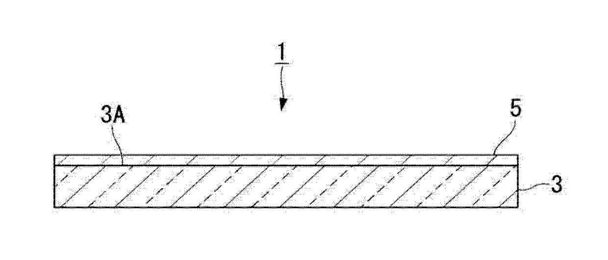
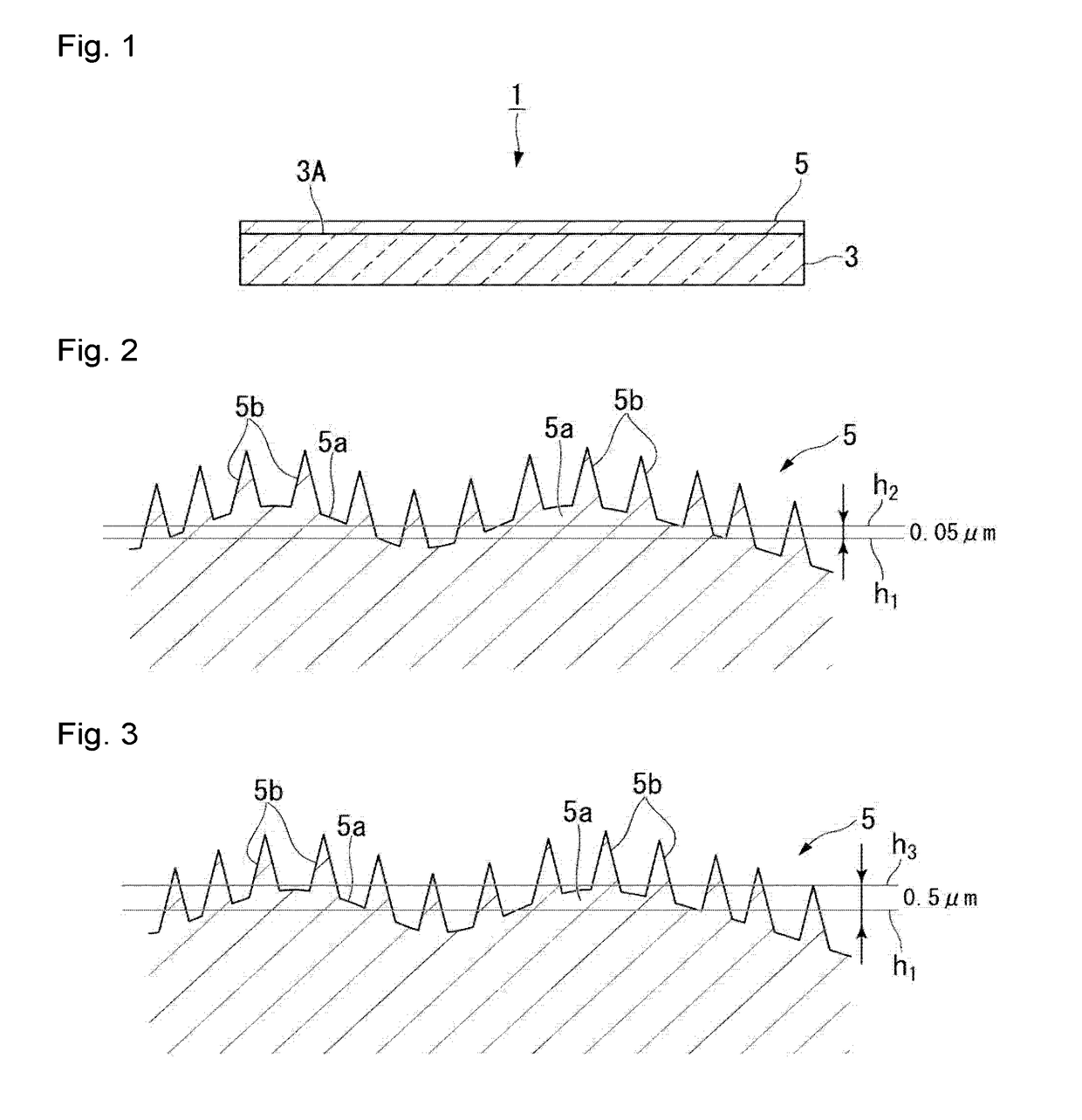
[0064]FIG. 1 is a cross-sectional view schematically illustrating a first embodiment of the translucent structure of the present invention. The translucent structure 1 according to this embodiment comprises a translucent substrate 3 and an antiglare film 5 formed on a first surface 3A of the translucent substrate 3. The antiglare film 5 has a concavo-convex structure on its surface. The surface of the antiglare film 5 constitutes the surface of the translucent structure 1. Accordingly, the translucent structure 1 has the above concavo-convex structure on its surface.

(Translucent Substrate)

[0065]The translucent substrate 3 is not limited so long as it can transmit visible light and is preferably transparent. Transparency with respect to the translucent substrate 3 means that it transmits light in a wavelength region of from 400 to 1,100 nm in an amount of at least 80% on average (that is, an average transmittance of at least 80%). The average transmittance with respect to light in a ...

second embodiment

[0299]FIG. 7 is a cross-sectional view schematically illustrating a second embodiment of the translucent structure of the present invention. FIG. 8 is a cross-sectional view schematically illustrating the surface shape of the translucent structure according to the present embodiment.

[0300]A translucent structure 2 according to the present embodiment comprises a translucent substrate 4. The translucent substrate 4 has a concavo-convex structure on a first surface 4a, and the concavo-convex structure has first convex portions 4a and second convex portions 4b.

[0301]The first surface 4A of the translucent substrate 4 constitutes the surface of the translucent structure 2. Accordingly, the translucent structure 2 has the concavo-convex structure on its surface.

[0302]The translucent substrate 4 is the same as the translucent substrate 3 according to the first embodiment except that it has the concavo-convex structure on the first surface, and the preferred embodiment is also the same.

[03...

third embodiment

[0313]FIG. 9 is a cross-sectional view schematically illustrating a third embodiment of the translucent structure of the present invention. FIG. 10 is a cross-sectional view schematically illustrating the surface shape of the translucent structure according to the present embodiment. In the following description, constituents corresponding to those in the already described embodiments are represented by the same symbols and their detailed description is omitted.

[0314]A translucent structure 6 according to the present embodiment comprises a translucent substrate 3, an antiglare film 5 formed on a first surface 3A of the translucent substrate 3, and a water / oil repellent layer 7 formed on the antiglare film 5.

[0315]The water / oil repellent layer 7 has a concavo-convex structure on its surface, and the concavo-convex structure contains first convex portions 7a and second convex portions 7b.

[0316]The surface of the water / oil repellent layer 7 constitutes the surface of the translucent s...


PUM


Abstract

To provide a translucent structure, which is excellent in the antiglare property, and which has its sparkle sufficiently suppressed.The translucent structure of the present invention has the following concavo-convex structure on its surface. The concavo-convex structure: having first convex portions having a diameter of larger than 10 μm in a cross section at a height of 0.05 μm+the bearing height of a surface shape obtained by measuring a region of 101×135 μm to 111×148 μm by a laser microscope, and second convex portions having a diameter of larger than 1 μm in a cross section at a height of 0.5 μm+the above bearing height of the surface shape; the average diameter of the first convex portions being larger than 10 μm and at most 185 μm in a cross section at a height of 0.05 μm+the above bearing height of the surface shape; the maximum height of the first convex portions being from 0.2 to 8 μm based on a height at the lowest portion in the above region; and the number of the second convex portions being from 0.0004 to 1.2 per 1 um2, and the average height of the second convex portions being from 0.1 to 8 μm based on the above bearing height.

Description

TECHNICAL FIELD[0001]The present invention relates to a translucent structure and an article.BACKGROUND ART[0002]With respect to an image display device (for example, a liquid crystal display, an organic EL display or a plasma display) attached to various equipment (for example, a television, a personal computer, a smart phone, a mobile phone or a vehicle), if outside light such as indoor lighting (such as fluorescent light) or sunlight is reflected in a display surface, visibility will decrease due to the reflected image.[0003]As a method to suppress reflection of outside light, a method of disposing an antiglare film having irregularities on its surface, on the display surface of an image display device to diffusely reflect the outside light thereby to blur the reflected image may be mentioned.[0004]As a method of forming an antiglare film, a method of applying a coating liquid containing a silica precursor such as a hydrolytic condensate of an alkoxysilane to a substrate by a spa...

Claims


Application Information

Patent Timeline
Patent Type & Authority Applications(United States)
IPC IPC(8): G02B1/113
CPCG02B1/113G02B5/0221G02B5/0231G02B5/0268G02B5/0278
Inventor TAKAI, AZUSAIKEDA, TORUKASHIWABARA, SATOSHITAKEDA, YOSUKE
Owner ASAHI GLASS CO LTD
Why Eureka
Try Eureka