
Method for joining terminal and electric wire and electric wire connection terminal

a technology of connecting terminals and electric wires, which is applied in the direction of connection contact materials, connections effected by permanent deformation, line/current collector details, etc., can solve the problems of increasing the number of steps for joining between a terminal and an electric wire, electric wires with lower strength, and mechanical joining undesirably weak, so as to avoid electric corrosion, increase the density of joining twisted wires, and increase the strength of joining

Inactive Publication Date: 2017-05-18
TABUCHI ELECTRIC CO LTD
View PDF3 Cites 1 Cited by
  • Summary
  • Abstract
  • Description
  • Claims
  • Application Information

AI Technical Summary

Benefits of technology

The patent text describes a method to join electric wires and terminals using a watertight sealing structure to prevent corrosion. The method involves crimping the wire under stress to increase the joining density of the twisted wires, and then soldering the wire onto the terminal to increase the strength of the joining. The terminal is made of a different material from the wire, so the terminal is surface-treated to avoid corrosion. The method ensures a mechanically stable and electrically stable connection between the wire and terminal, even if they are made of different materials.

Problems solved by technology

However, in a case where an electric wire made of aluminum or the like is joined to a terminal by crimping connection involving pressurizing and heating the electric wire as in Patent Documents 1 and 2, the electric wire, which has lower strength than copper and the like, is sometimes broken due to the pressurizing, and therefore mechanical joining is undesirably weak.
Furthermore, using a watertight sealing structure to prevent electric corrosion as in Patent Document 1 increases the number of steps for joining between a terminal and an electric wire and complicates a terminal structure.

Method used


Image

  • Method for joining terminal and electric wire and electric wire connection terminal
  • Method for joining terminal and electric wire and electric wire connection terminal
  • Method for joining terminal and electric wire and electric wire connection terminal

Examples


Embodiment Construction

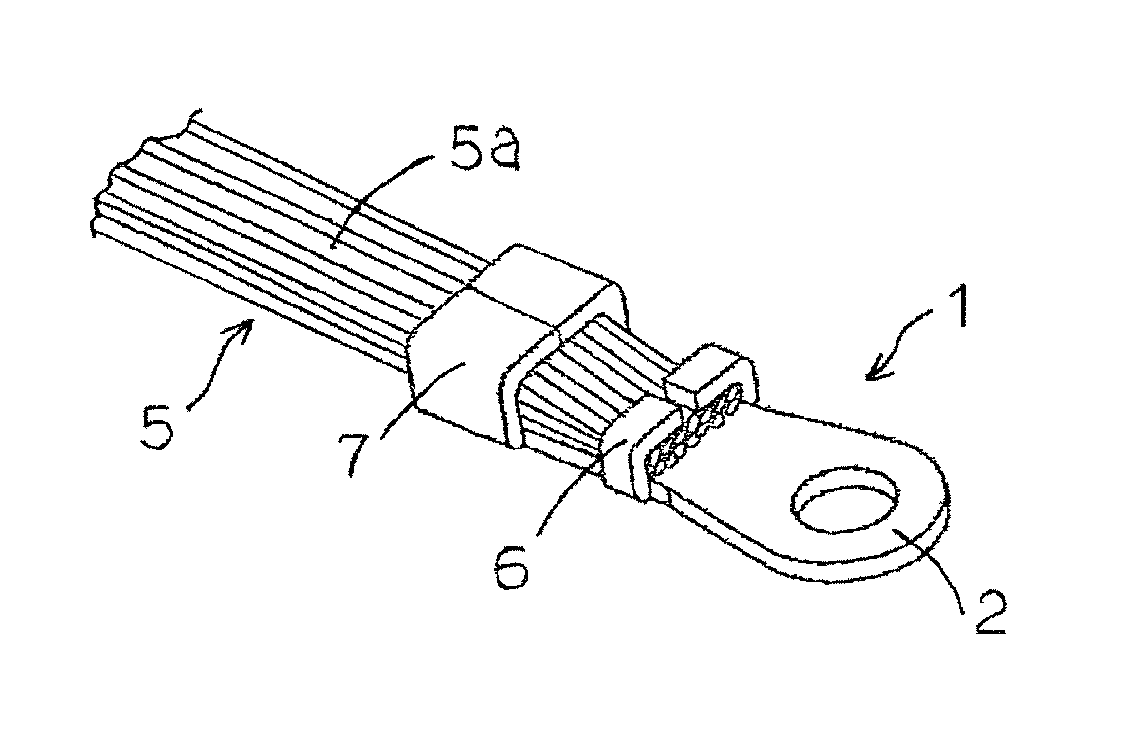
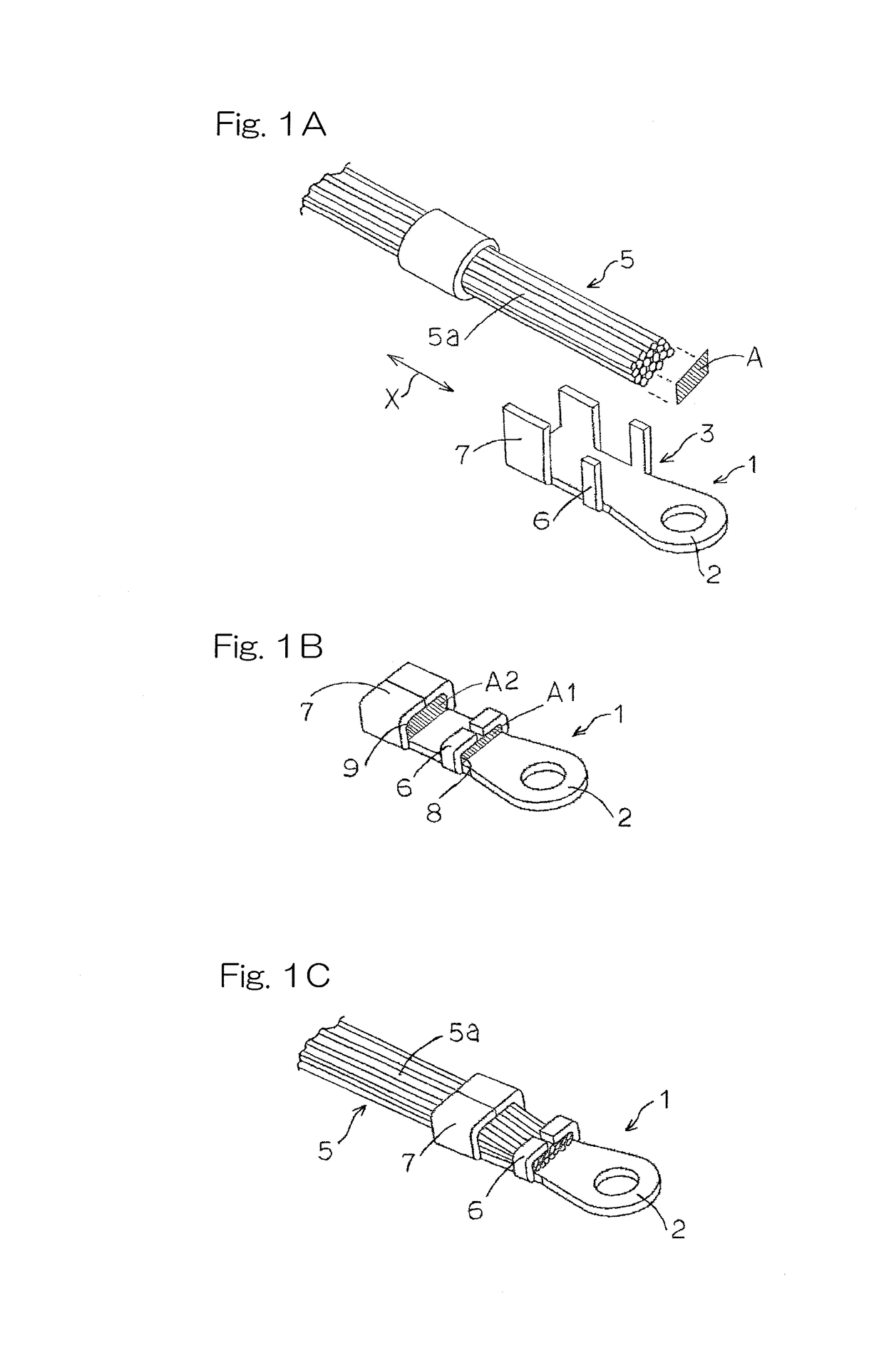
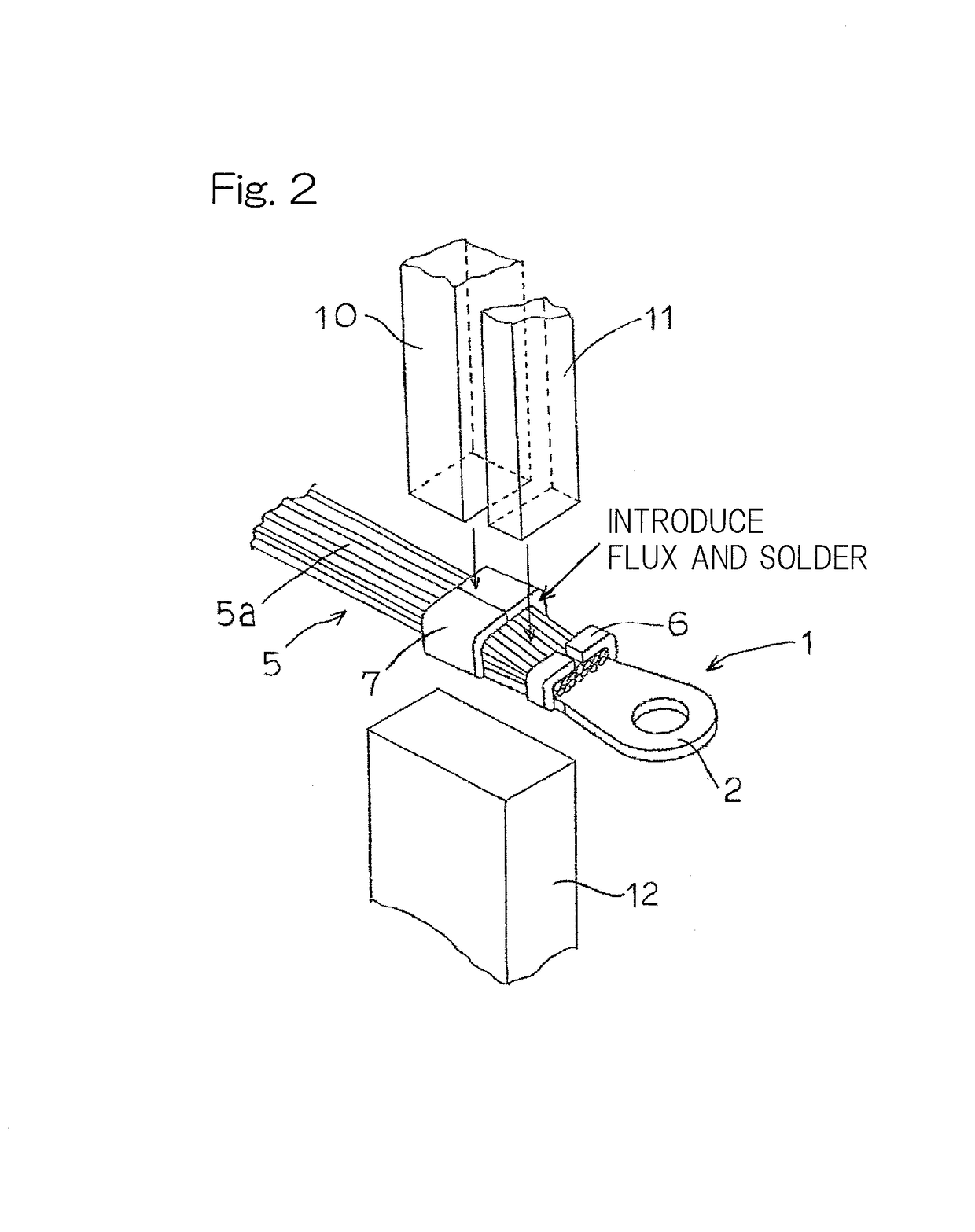
[0033]A preferred embodiment of the present invention is described below with reference to the drawings. FIG. 1A is a developed view illustrating a terminal for electric wire connection according to an embodiment of the present invention. FIG. 1B is a perspective view illustrating the terminal for electric wire connection, and FIG. 1C is a perspective view illustrating a completed state of connection between the terminal and the electric wire. FIG. 2 is a perspective view illustrating a state of joining between the terminal and the electric wire. As illustrated in FIG. 1A, a terminal 1 is made of a material different from an electric wire 5 and includes a connector part 2 and an electric wire connection part 3 for connecting the electric wire 5 by soldering. As illustrated in FIG. 1B, the electric wire connection part 3 includes a first crimp piece 6 and a second crimp piece 7. As illustrated in FIG. 1C, the electric wire 5 is joined to the terminal 1 in a state where the electric w...


PUM


Abstract

A method of the present invention includes: electrically joining an electric wire 5 and a terminal (1) by crimping the electric wire 5 held by a first crimp piece (6) under a stress condition where external force is applied; and mechanically joining the terminal (1) and the electric wire (5) by soldering the electric wire (5) held by a second crimp piece (7) onto the terminal (1) while heating the electric wire (5) under a stress-free condition where no external force is applied by applying an electric current to heating electrodes (10, 12). The terminal (1) that is made of a different material from the electric wire (5) is surface-treated in order to avoid electric corrosion with the electric wire (5).

Description

CROSS REFERENCE TO THE RELATED APPLICATION[0001]This application is a continuation application, under 35 U.S.C. §111 (a) of international application No. PCT / JP2014 / 070264, filed Jul. 31, 2014.BACKGROUND OF THE INVENTION[0002]Field of the Invention[0003]The present invention relates to a method for joining a terminal and an electric wire, and a terminal for electric wire connection, in a case where the terminal and the electric wire are made of different materials.[0004]Description of Related Art[0005]Conventionally, an electric wire made of copper or a copper alloy is often used. Meanwhile, aluminum or an aluminum alloy has good electric conductivity and is lighter in weight and lower in cost than copper and the like, and therefore there are a lot of advantages when aluminum or the like is used for an electric wire.[0006]However, in a case where aluminum or the like is used for an electric wire, the electric wire needs to be joined to a terminal made of a different material such as...

Claims


Application Information

Patent Timeline
Patent Type & Authority Applications(United States)
IPC IPC(8): H01R4/18H01R11/12H01R43/048H01R4/62H01R43/02
CPCH01R4/187H01R4/625H01R11/12H01R43/048H01R4/184H01R43/02H01R4/023H01R43/0484H01R4/02H01R4/18H01R4/62
Inventor TAMURA, AKIMASAKUNIMI, TAKENORIKYO, NOBUHITOSHINDO, SACHIHIKOADACHI, TAKEHIKO
Owner TABUCHI ELECTRIC CO LTD
Learn More