
Exhaust purification device

a technology of exhaust purifier and purifier, which is applied in the direction of vehicle heating/cooling devices, machines/engines, vehicular safety arrangements, etc., can solve the problems of reducing the denitration rate of nox catalyst by accumulation of dust, accumulating temporary dust, and unable to remove residual dust by injecting compressed air, etc., to achieve a reduction in the denitration rate of nox catalyst by accumulation of dust, reducing the denitration rate of nox catalyst by accumulation

Inactive Publication Date: 2017-05-25
YANMAR POWER TECHNOLOGY CO LTD
View PDF13 Cites 2 Cited by
  • Summary
  • Abstract
  • Description
  • Claims
  • Application Information

AI Technical Summary

Benefits of technology

The present invention relates to a method for maintaining the performance of a NOx catalyst in an engine. The invention involves monitoring the operation of the engine and analyzing the accumulation of dust on the catalyst. By detecting abnormal degradation of the catalyst and performing suitable treatments, such as exchange or manual washing, the invention prevents the catalyst from becoming ineffective over time due to dust accumulation. This helps to maintain the engine's ability to reduce nitrogen oxide emissions.

Problems solved by technology

However, in the exhaust purifier, residual dust which cannot be removed by injecting the compressed air is accumulated temporarily.
Namely, there is a problem in the exhaust purifier that temporal lowering of the denitration rate of the NOx catalyst cannot be suppressed by normal injection of the compressed air.

Method used


Image

  • Exhaust purification device
  • Exhaust purification device
  • Exhaust purification device

Examples


Embodiment Construction

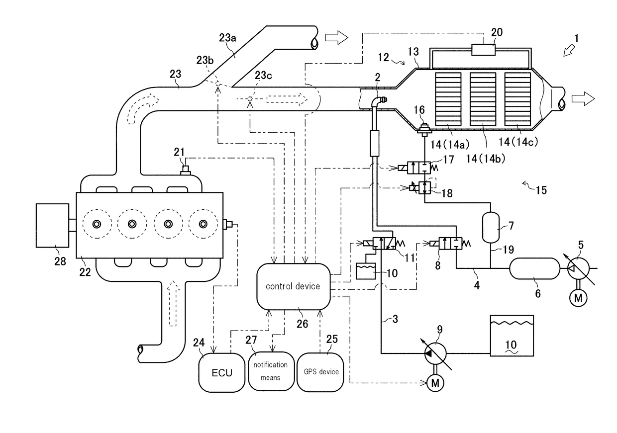
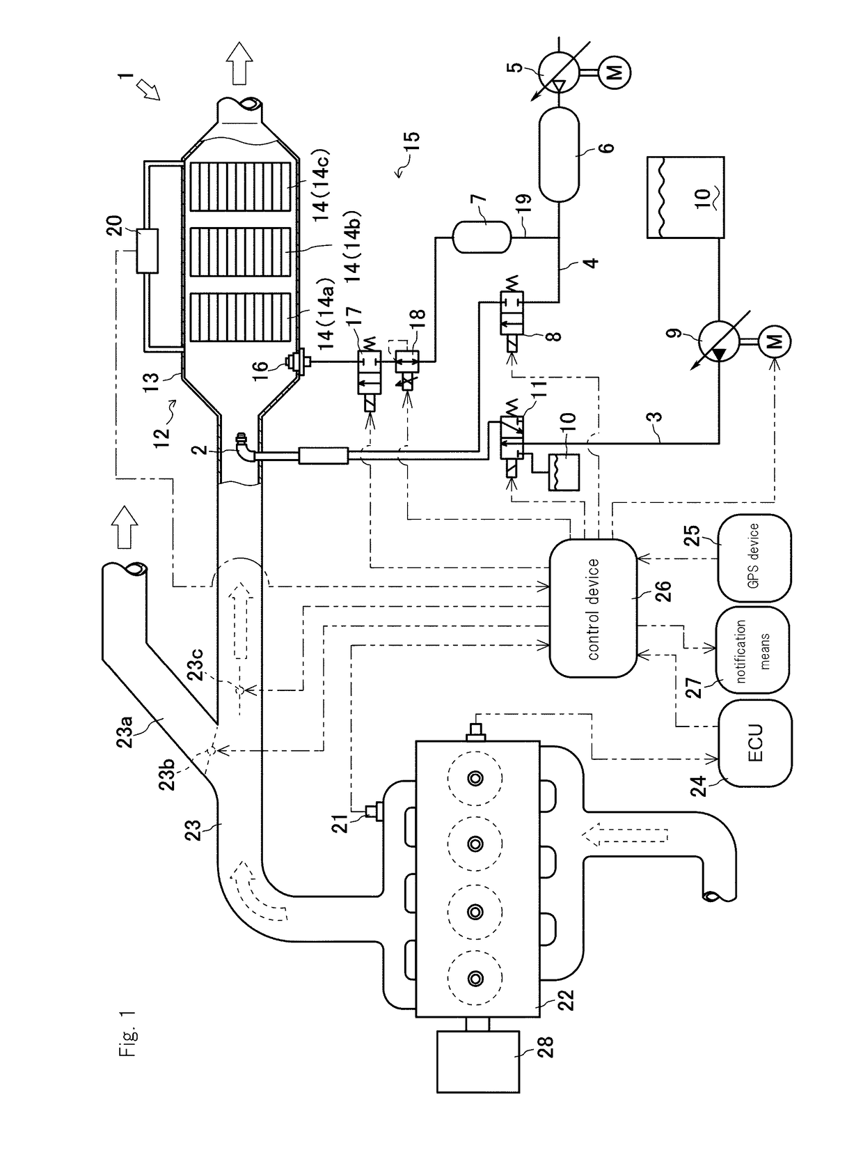
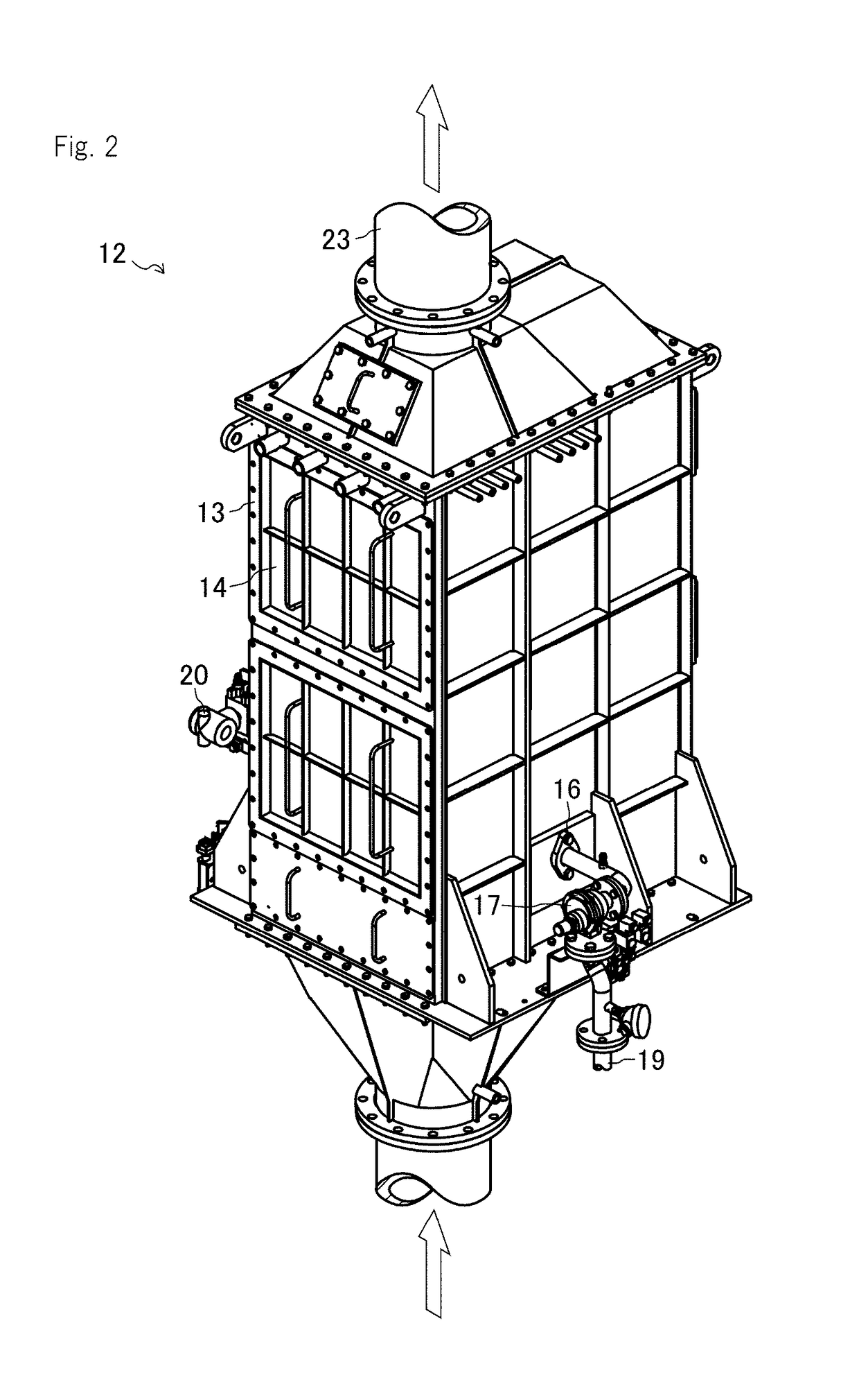
[0030]Below, referring to FIGS. 1 to 4, an exhaust purifier 1 which is a first embodiment of an exhaust purifier according to the present invention is explained. In this embodiment, an “upstream side” means an upstream side in a flow direction of fluid, and a “downstream side” means a downstream side in the flow direction of the fluid. The exhaust purifier 1 is not limited to this embodiment and may alternatively be airless type which does not use pressurized air.

[0031]As shown in FIG. 1, the exhaust purifier 1 purifies exhaust gas discharged from an engine 22 which is an internal combustion engine driving a generator 28. The exhaust purifier 1 is provided in an exhaust pipe 23 of the engine 22. The exhaust purifier 1 has a urea water injection nozzle 2, a urea supply passage 3, a first air supply passage 4, a pressurized air supply pump 5 (compressor), an air tank 6, a urea air valve 8, a urea water supply pump 9, a switching valve 11, a catalyst reactor 12, a soot blower 15, a pre...


PUM


Abstract

The invention provides an exhaust purification device capable of suppressing the temporal decrease in NOx catalyst removal efficiency due to soot accumulation. The invention provides an exhaust purification device using an air injection nozzle to inject pressurized air into a casing of a catalyst reactor containing an NOx catalyst as a catalyst and removing soot adhering to the NOx catalyst, wherein it is determined and externally notified that there is abnormal deterioration in the NOx catalyst when the pressure difference ΔP in exhaust between the upstream and downstream sides of the NOx catalyst has increased by at least a first reference pressure difference increase ΔPt1, which is the allowable amount of pressure difference increase, above the pressure difference ΔPi in exhaust between the upstream and downstream sides of the catalyst in the initial state at the same exhaust flow rate Ve.

Description

TECHNICAL FIELD[0001]The present invention relates to an exhaust purifier of an internal combustion engine.BACKGROUND ART[0002]Conventionally, an exhaust purifier which reduces NOx to nitrogen and water with a catalyst reactor in which a selective reduction NOx catalyst (SCR catalyst) is arranged and ammonia which is a reducing agent so as to decrease NOx (nitrogen oxide) included in exhaust gas from an internal combustion engine is known. The ammonia is generated by urea water injected to exhaust gas with high temperature and contacts the NOx catalyst so as to reduce NOx to nitrogen and water.[0003]In the exhaust purifier, a material having a carrier of oxides, such as Ti including active ingredients, such as V and Cr which is formed to be a honeycomb structure in which many through holes are formed is used as the NOx catalyst of the catalyst reactor. According to the configuration, a contacting area is increased so as to promote a reduction reaction. On the other hand, when exhaus...

Claims


Application Information

Patent Timeline
IPC IPC(8): F01N3/20F02D41/02F01N3/10
CPCF01N3/20F02D41/027F01N3/103F01N3/08F02D41/22F02D43/00F02D45/00B60H1/12B60R13/0884B60R19/02F01N3/2066F01N3/208F01N3/2093F01N3/30F01P5/02F02B13/02F01K19/08F01N3/0233F02M35/06F23D14/52F23D14/82B01D2239/0622B60R2019/184B60R2019/188F01N2550/02F01N2560/026F01N2560/08F01N2610/02F02B2720/257F02D2250/08Y02A50/20Y02T10/12Y02T10/40
Inventor FUKUI, YOSHINORI
Owner YANMAR POWER TECHNOLOGY CO LTD
Learn More