A method for automatic blood flow control, automatic blood flow control system and a tourniquet

a technology of automatic blood flow control and control system, applied in the direction of tourniquets, sensors, etc., can solve the problems of loss of blood flow, significant effort of staff, and potential permanent damag

Inactive Publication Date: 2017-06-01
INST KARDIOLOGII IM PRYMASA TYSIACLECIA
View PDF5 Cites 5 Cited by
  • Summary
  • Abstract
  • Description
  • Claims
  • Application Information

AI Technical Summary

Benefits of technology

[0017]The advantage of the invention is to automate the compression of the punctured vessel, in a manner ensuring both hemostasis and flow in the compressed vessel, while continuously monitoring the status of homeostasis and patency of the vessel.

Problems solved by technology

Using too much pressure may cause crushing the vessel, resulting in loss of blood flow, resulting in the potential permanent damage due to thrombosis, obstruction and even a possible limb ischemia.
Such a solution requires a significant effort of staff and is associated with a risk of leading to loss of blood through too fast loosening of compression on the damaged vessel.
In such conditions—for example—precise measurement of systolic and diastolic pressure is not possible.
Without the ability to automatically adjust the compression on both vessels and automatic response to limb ischemia and pressure changes in the healing vessel such a blood flow increase would have a high risk for the patient.

Method used


Image

  • A method for automatic blood flow control, automatic blood flow control system and a tourniquet
  • A method for automatic blood flow control, automatic blood flow control system and a tourniquet
  • A method for automatic blood flow control, automatic blood flow control system and a tourniquet

Examples


first embodiment

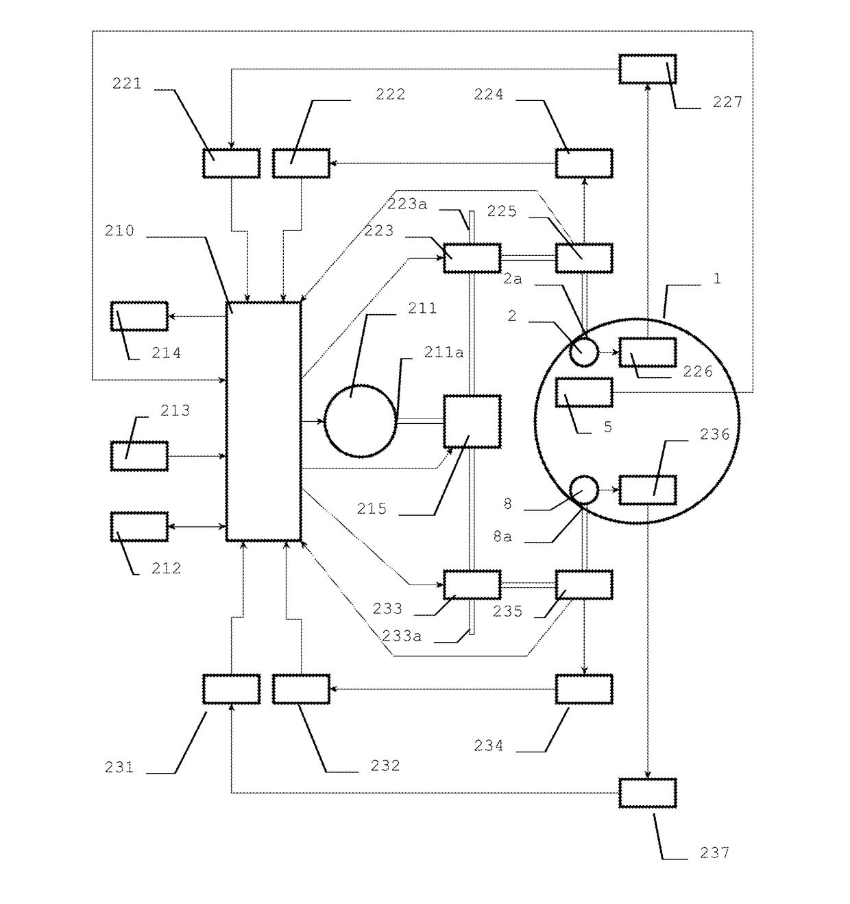
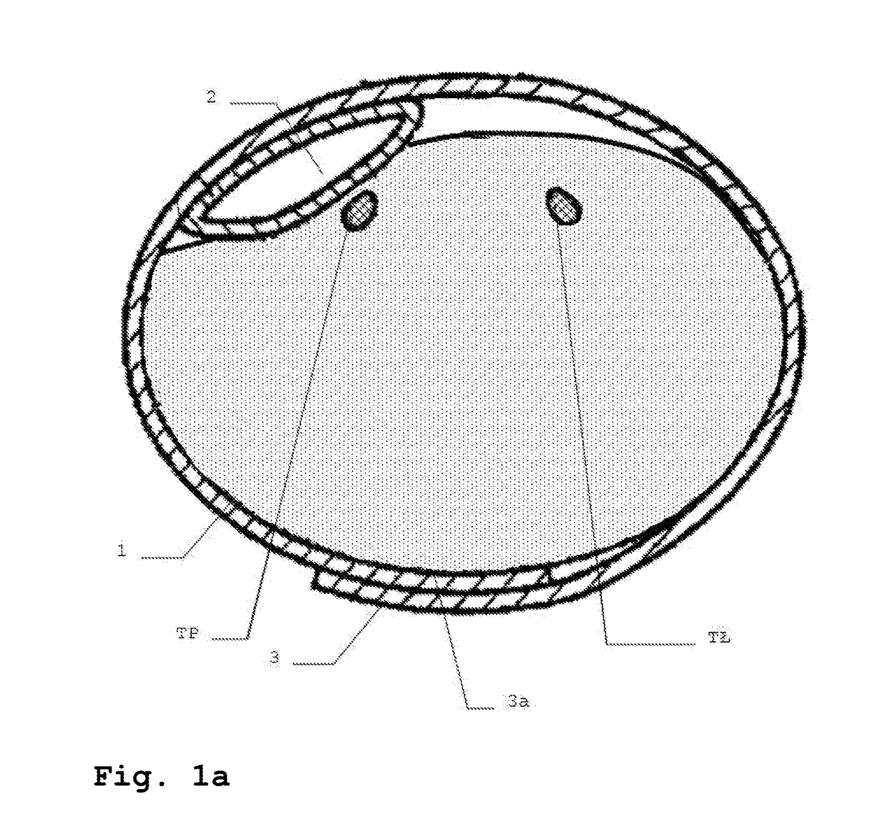
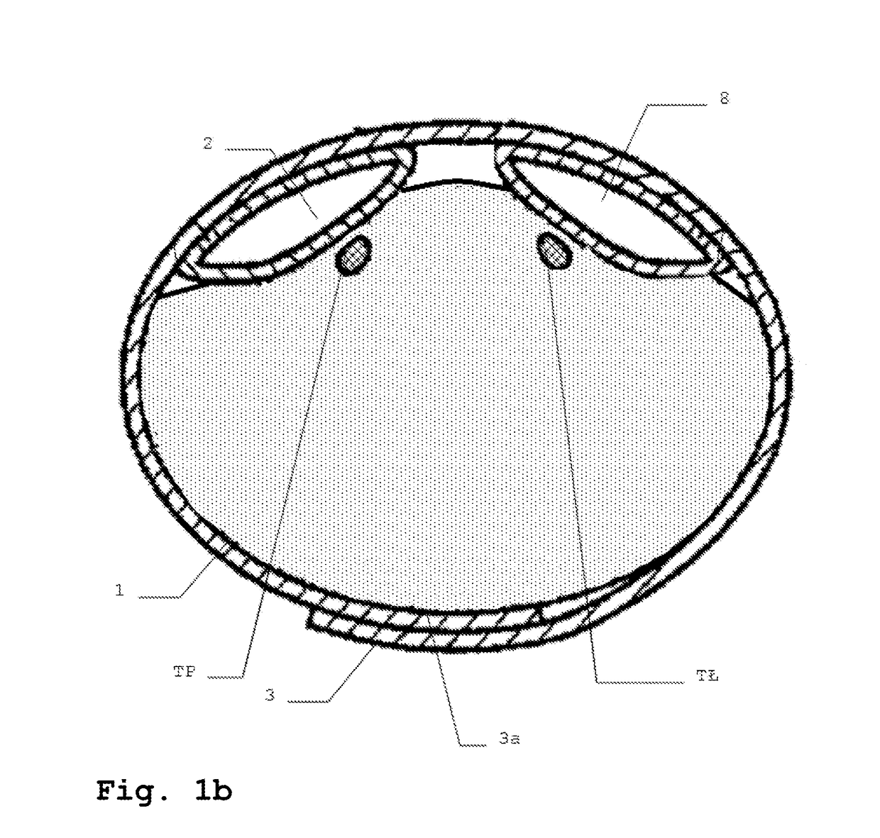
[0027 of the invention provides a bandage shown as a cross-section view in FIG. 1a, in the form of an arterial tourniquet, designed for attaching to the wrist, in a place where radial artery RA and ulnar artery UA are on the opposite sides of the wrist. Arterial tourniquet is provided with the tourniquet body 1 made of the transparent strip of flexible material wrapped around the wrist and provided with a first fastening element 3 and a second fastening element 3a, located on the opposite faces of the strip, from the outside and from the inside, respectively. Performing the tourniquet of transparent material allows easy inspection of the dressed place. The first and second fastening element 3 and 3a are made of an adhesive material, preferably a velcro strip. On the inner side the tourniquet 1 is provided with a first compression element, compressing the radial artery which is usually punctured during vascular surgeries. It is a balloon 2 filled with gas via a tubular connection on ...


PUM


Abstract

The subject of the invention is a method for automatic control of blood from the damaged vessel to be used in a dressing system provided with a tourniquet, a bandage and the first compression element. The method comprises the stage of applying pressure exceeding the systolic blood pressure of the patient via the compression element to a lesion site, so that the blood stops flowing through the damaged vessel, then the stage of reducing the pressure. In the pressure reduction stage, the pressure is reduced by a predetermined drop value, wherein if no blood flow is detected in the damaged vessel, then pressure reduction stage is repeated and if blood flow in the damaged vessel is detected, the pressure reduction stage is interrupted for a pressure drop time. Moreover, the subject of the invention is an automatic compression bandage system according to the invention is provided with a tourniquet with a compression element adapted to compress the damaged blood vessel at the lesion site, provided with an interface for electronic pressure control, and a CPU provided with a memory, connected to the compression element interface. The system is further provided with means for detecting the blood flow through the compressed vessel and means adapted for detecting the blood flow from compressed vessel. Moreover, the subject of the invention is a tourniquet to be used in the system according to the invention, provided with a controlled compression element and comprising a blood flow sensor and a blood loss sensor.

Description

TECHNICAL FIELD[0001]The subject of the invention is a method for automatic blood control, automatic blood control system and a tourniquet. More particularly, the invention relates to dressing blood vessels, especially arteries damaged for the purpose of endovascular procedures.PRIOR ART[0002]Prior art discloses compression bandages, applicable when removing the arterial sheath after a cardiac catheterization—angiography, catheter ablation, or after other procedures that require reaching blood pressure, i.e., generally endovascular procedures. These include a tourniquet known from Polish patent application No. P.396805 and International Patent Publication No. WO2013060883.[0003]These previously known solutions, capable of achieving the desired homeostasis often require implementation of a series of consecutive and successive actions, and often cooperation of at least two people during and after the procedure—usually a doctor and a nurse. These activities include putting a tourniquet...

Claims


Application Information

Patent Timeline
Patent Type & Authority Applications(United States)
IPC IPC(8): A61B17/135A61B17/132
CPCA61B17/1355A61B2562/00A61B17/1322A61B17/132A61B17/135
Inventor KRUK, MARIUSZ
Owner INST KARDIOLOGII IM PRYMASA TYSIACLECIA
Why Eureka
Try Eureka