High contrast projection screen

a projection screen and high contrast technology, applied in the field of projection screens, can solve the problems of high cost of low-cost projectors, short-distance projection lenses and/or vertical projection lenses, etc., and achieve the effects of high brightness, high transparency for external view, and high brightness

Inactive Publication Date: 2017-06-01
ISHII FUSAO
View PDF5 Cites 13 Cited by
  • Summary
  • Abstract
  • Description
  • Claims
  • Application Information

AI Technical Summary

Benefits of technology

[0012]It is an aspect of the present invention that the front-end projection screen for reflecting the incident image light beams has hologram formed on a flat surface which absorbs incident lights except very narrow wavelengths coinciding with the wavelengths of the incoming projected lights and changes the direction of reflected lights to horizontal parallel light beams directing to the viewer. The reflectance coefficient is very high when the wavelength of incident light and the designed spectrum of reflectance by the hologram are close. Hologram can also have a function of bending lights as if it forms a free shaped mirror to focus incident lights toward viewers. Because of narrow band of wavelength of reflection, the majority of ambient lights are absorbed and high contrast can be achieved even in a bright room.
[0013]It is another aspect that the present invention provides a front and rear projection display systems with free shaped mirrors in a projection optical system. A reflecting surface of hologram can be designed to reflect specified bands of wavelength of light and to bend the direction of reflected lights so that the hologram can be used as a free shaped mirror. Especially short distance projection lens and / or vertical projection lens are very costly and often prohibit the use for low cost projectors. This invention enables to reduce the cost of such expensive free shaped mirrors with flat low cost hologram.
[0015]It is another aspect that the present invention provides a method of manufacturing a projection screen by exposing photo-sensitive material with scanning laser beams using deflectable micromirrors with adjustable and desired incident angles of laser beams, so that large size screen plates can be produced.
[0016]It is another aspect that the present invention provides a high brightness screen for HUD (head-up-display), although maintaining high transparency for external view. This invention is also very useful to avoid dual images created by the two surfaces of screen plate.
[0017]In yet another aspect, the present invention provides a high brightness screen to project the image of the display of mobile phone on to windshield of automobile maintaining good transparency of external view, so that a drive can see both external view and the image of mobile phone's display without ghost images.
[0018]Briefly in a preferred embodiment, this invention discloses a reflecting screen that has a reflecting surface. The reflecting surface includes hologram which is designed to reflect narrow bands of lights and also focus the reflected lights toward viewers. This invention also discloses to make free shaped lens and / or mirrors with hologram inexpensively.

Problems solved by technology

Especially short distance projection lens and / or vertical projection lens are very costly and often prohibit the use for low cost projectors.

Method used


Image

  • High contrast projection screen
  • High contrast projection screen
  • High contrast projection screen

Examples


Embodiment Construction

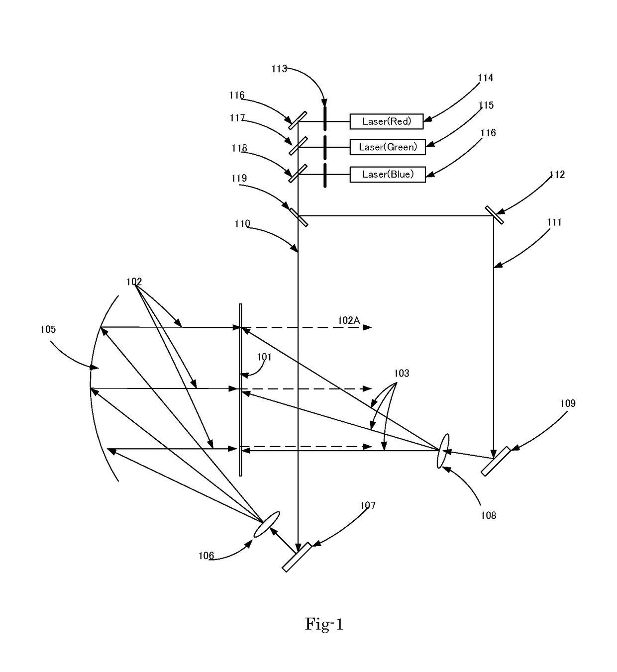
[0040]FIG. 1 is a system diagram of an image display apparatus as an exemplary embodiment of this invention that illustrates how to record hologram. The image display apparatus as shown in FIG. 1 comprises laser light sources 114, 115 and 116. The laser light sources emit laser lights having coherence length long enough to create interference on a display screen 101. The display screen 101 is coated with a photographic film (not specifically shown). The photographic film is usually composed of photopolymer, photoresist or silver halide emulsion coated on a plate or film. In this embodiment, the laser lights source are implemented to emit primary colors comprise Blue, Green and Red laser lights. The image display system further includes a shutter 113 to block a laser beam when that laser beam is not needed. Each laser unit has a shutter, so that each laser can be controlled independently. The image display system further includes a mirror 116 to change the direction of laser beam. Th...


PUM


Abstract

An image display system includes a reflecting screen that has a reflecting surface. The reflecting surface includes hologram which reflects narrow bands of spectrum of incident lights toward desired direction. A projection display system includes a reflecting mirror(s) with hologram so that the image can be projected nearly vertical or short distance. This invention can be used as a head-up-display with improved brightness and eliminating ghost noise.

Description

CROSS REFERENCE TO RELATED APPLICATIONS[0001]This application is a Non-Provisional Application and claims the Priority Date of previously filed Provisional Application 61 / 855,948 filed on May 28, 2013. This Application is also a Continuation in Part (CIP) Application of another application Ser. No. 11 / 285,881 filed on Nov. 23, 2005 and issued into U.S. Pat. No. 7,595,828.TECHNICAL FIELD[0002]This invention relates to a display system for projecting an image on a screen. More particularly, this invention relates to projection screens with improved image quality by using wavelength selective reflecting film including at least one of hologram, multi-layer dielectrics and cholesteric liquid crystal as a screen to reflect only selected wavelengths of light to improve the brightness and contrast of images. This invention also improves the image quality of head-up-display (hereafter“HUD”) using a wavelength selective screen with improved brightness.BACKGROUND OF THE INVENTION[0003]Image di...

Claims


Application Information

Patent Timeline
Patent Type & Authority Applications(United States)
IPC IPC(8): G02B27/01G03B21/56G03B21/62G02B27/00G03H1/04
CPCH04M1/72527H04M1/72583G02B27/0101G02B27/0103G02B27/0018G03H1/0465G03H2001/2239G03B21/567G02B2027/0109G02B2027/0112G02B2027/0118G03H2001/2231G03B21/62G02B2027/0116G02B2027/0127G02B2027/011H04M1/0272H04M2250/54G03H2001/0478G03H1/0248G03B21/10G03B21/28G03H2222/18G03H2222/36G03H2001/0439
Inventor ISHII, FUSAO
Owner ISHII FUSAO
Why Eureka
Try Eureka