
Image processing apparatus and image processing method

Active Publication Date: 2017-06-01
CANON KK
View PDF7 Cites 4 Cited by
  • Summary
  • Abstract
  • Description
  • Claims
  • Application Information

AI Technical Summary

Benefits of technology

The present invention aims to provide a new way to reduce fixed-pattern noise in images captured by the same image sensor. This technique can help to improve the quality of the captured images.

Problems solved by technology

The related art described above, however, has the following problems.
When filter type methods such as the representative example disclosed in Japanese Patent Application Laid-open No. 2007-128009 are applied to an out-of-focus image group, a problem may occur in that image quality of a generated image deteriorates due to fixed-pattern noise attributable to an image sensor.
This problem becomes conspicuous when image magnification and reduction (changes in scale) among images constituting the out-of-focus image group is significantly small, or in other words, in the case of a group of images in which fixed-pattern noise appears in the images at approximately the same positions.
However, this method cannot be applied to improve image quality when an all-in-focus image is obtained from an out-of-focus image group which has already been photographed.
While problems that occur in an out-of-focus image group have been described above, a similar problem may also occur in a group of images such as moving image data that is photographed by a same optical system.
However, since this method is constituted by a simplified process which involves estimating as fixed-pattern noise a difference image obtained by subtracting an average value from a relatively flat region, then estimation accuracy of the fixed-pattern noise is low.
Therefore, in principle, it is difficult to realize reduction of fixed-pattern noise with high accuracy in image data including images of various objects.
In addition, multiplicative fixed-pattern noise other than additive fixed-pattern noise, for example, that is attributable to a variation in sensitivity of a light receiving unit among cells of an image sensor or a variation in gain of an amplifier, cannot be reduced.

Method used


Image

  • Image processing apparatus and image processing method
  • Image processing apparatus and image processing method
  • Image processing apparatus and image processing method

Examples


first embodiment

[0026](Overall System Configuration)

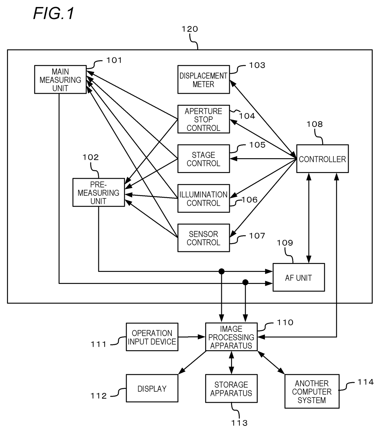
[0027]In a first embodiment, an example in which the present invention is applied to a virtual slide system configured as shown in FIG. 1 will be described.

[0028]The virtual slide system is constituted by an imaging apparatus (also referred to as virtual slide scanner) 120 which acquires imaging data of a specimen, an image processing apparatus (also referred to as host computer) 110 which performs data processing and control of the imaging data, and peripheral apparatuses of the image processing apparatus 110.

[0029]An operation input device 111 such as a keyboard and a mouse which receives an input from a user and a display 112 which displays a processed image are connected to the image processing apparatus 110. In addition, a storage apparatus 113 and another computer system. 114 are connected to the image processing apparatus 110.

[0030]When imaging of a large number of specimens (slides) is performed by batch processing, the imaging apparatus 1...

second embodiment

[0101]The first embodiment describes a method of reducing fixed-pattern noise in a case where additive fixed-pattern noise that is independent of an image component of an image of an object has been added to an out-of-focus image group. However, fixed-pattern noise also includes fixed-pattern noise dependent on a variation in sensitivity among cells of an image sensor or a variation in gain of an amplifier. Such fixed-pattern noise has intensity that is dependent on an amount of charge accumulated in a cell of the image sensor or, in other words, dependent on an image component of an image of an object, and is referred to as multiplicative fixed-pattern noise.

[0102]An out-of-focus image group yk (k=1, . . . , M) to which multiplicative fixed-pattern noise has been added can be expressed by the following expressions.

yk=ok+nk(k=1, . . . ,M)  (12)

(nk)i,j=(v)i,j·(ok)i,j, i,jε{1, . . . ,N}, kε{1, . . . ,M}  (13)

[0103]By arranging Expressions (12) and (13), the out-of-focus image group yk...

third embodiment

[0127]When fixed-pattern noise is multiplicative noise, multiplicative noise can be treated as additive noise by applying an appropriate transformation to an image, and fixed-pattern noise can be reduced using the fixed-pattern noise reduction process described in the first embodiment. Hereinafter, a method of reducing multiplicative fixed-pattern noise will be described.

[0128]By taking the logarithm of both sides of Expression (14), the following expression is derived.

log((yk)i,j)=log((ok)i,j)+log({1+(v)i,j}), i,jε{1, . . . ,N}, kε{1, . . . ,M}  (23)

[0129]In other words, by taking the logarithm of brightness of each image of an out-of-focus image group, multiplicative fixed-pattern noise can be converted to additive fixed-pattern noise which is not dependent on a focusing position (k).

[0130]FIG. 6 is a flow chart showing a fixed-pattern noise reduction process according to the present embodiment. Processing according to the present embodiment will now be described with reference to...


PUM


Abstract

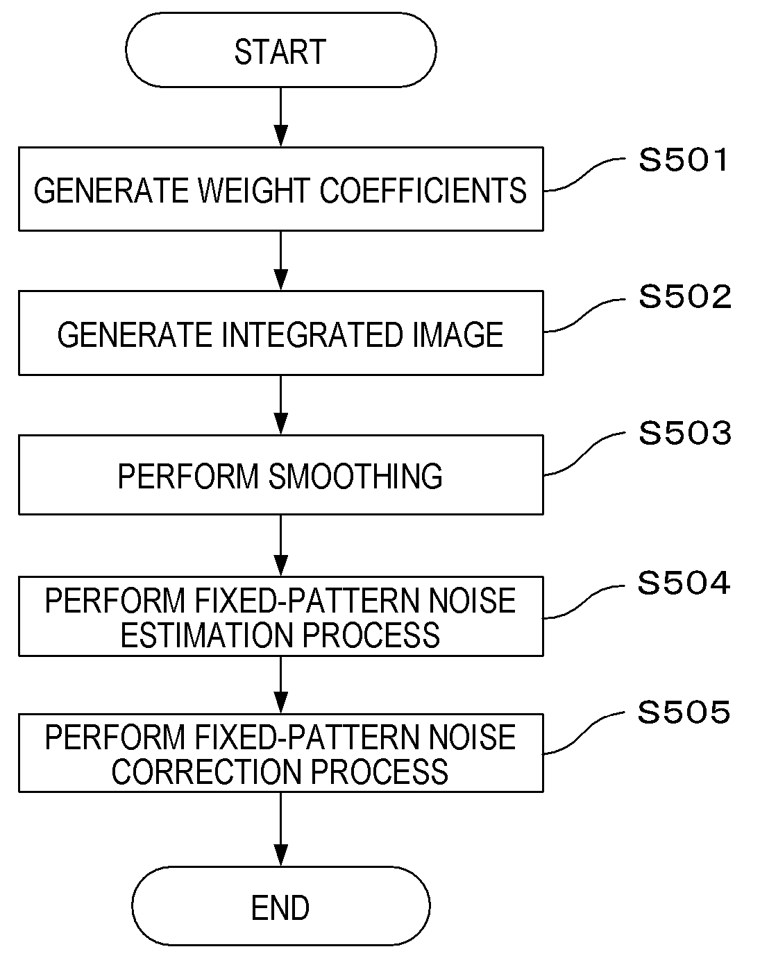
An image processing method includes the steps of: generating, based on data of a plurality of images acquired by performing imaging using a same image sensor, a weight coefficient corresponding to each image so that a weight coefficient corresponding to an image of which a brightness change is smooth is relatively large; integrating the data of the plurality of images using the weight coefficients to generate data of an integrated image; applying smoothing to the data of the integrated image to generate data of a smoothed integrated image; and generating, based on the data of the integrated image and the data of the smoothed integrated image, data of estimated fixed-pattern noise which is an estimated value of fixed-pattern noise attributable to the image sensor.

Description

BACKGROUND OF THE INVENTION[0001]Field of the Invention[0002]The present invention relates to a technique for reducing fixed-pattern noise included in a group of images constituted by a plurality of images (for example, a plurality of images photographed by changing focusing positions, or moving image data) to enhance image quality.[0003]Description of the Related Art[0004]Techniques are known in which an arbitrary viewpoint image or an arbitrary out-of-focus image is generated, through restoration of a light beam space, from a group of a plurality of images that are obtained through an imaging optical system of a camera, a microscope, etc. photographing an object by changing focusing positions (such an image group is hereinafter referred to as an out-of-focus image group). For example, Japanese Patent Application Laid-open No. 2007-128009 discloses a method of generating an arbitrary viewpoint image or an arbitrary out-of-focus image by performing a coordinate transformation proces...

Claims


Application Information

Patent Timeline
IPC IPC(8): G06T5/00G02B21/36G06T5/20G06T11/60G06T5/50
CPCG06T5/002G06T11/60G06T5/50G06T5/20G02B21/365G06T2207/20182G06T2207/10056G06T2207/20021G06T2207/10016G06T2207/10148G06T2207/20024G06T2207/20221G06T5/70
Inventor MURAKAMI, TOMOCHIKAKODAMA, KAZUYA
Owner CANON KK
Learn More