
Low cost ventricular device and system thereof

Active Publication Date: 2017-06-08
CARDIOBIONIC PTY LTD
View PDF6 Cites 11 Cited by
  • Summary
  • Abstract
  • Description
  • Claims
  • Application Information

AI Technical Summary

Benefits of technology

The present invention aims to create a low-cost or easy-to-manufacture LVAD that reduces or minimizes the risks of hemolysis (when red blood cells break open) or blood clotting.

Problems solved by technology

This leads many implantable left ventricular assist devices (LVADs) to be over-engineered and being extremely expensive to manufacture.
All of these exotic metals are relatively expensive to machine and difficult manufacture.
Additionally, there have been many previous inventions that target short term usage (typically less than 6 hours) and are typically not implantable.
Also these inventions tend to be only suitable for applications during heart bypass operations or similar emergency situations.
However, many of these types of devices fail to reduce shearing forces on the pumping fluid.
The previous short term devices typically result on patient complications or serious adverse events occurring for usage extending beyond about 8-12 hours.
Also many of these short devices rotate at higher relative levels of rotations per minute (RPM) than the longer term devices and this may further exasperate the haemolysis effect.
One of the disadvantages with this invention is that as the pump housing is entirely constructed of metal, electrical eddy currents form between the motor stators and permanent magnets positioned within the impeller.
These electrical eddy currents significantly reduce the electrical efficiency of the blood pump and may lead to increased power consumption.
One of the disadvantages with the structural members being comprised of ceramic material is that ceramic material is relatively expensive and difficult to construct.
The ceramic material may include a diamond like coating which may be particularly costly to produce and prone to flaking.
This device includes an impeller of a difficult manufacturing shape with dimensional stability issues relating to the tights tolerances of the impeller blades in relation to the housing.
Minor dimension changes in use or in moulding of this invention may possibly lead to pump stop or clotting issues.
However, pumps that are entirely constructed of polymeric materials may lack the desired: wear resistance or strength, fluid impermeability and bio-resistance necessary for this type of application.
These types of pumps commonly warp or distort due to fluid absorption limiting their usefulness.

Method used


Image

  • Low cost ventricular device and system thereof
  • Low cost ventricular device and system thereof
  • Low cost ventricular device and system thereof

Examples


second embodiment

[0127]Second and third embodiments of the present invention are depicted in FIGS. 4-11. In the second embodiment, an alternative impeller 40 has been provided. This impeller 40 is adapted to rotate in the direction 53 in FIG. 6. The impeller includes at least three blades 44 and preferably these blades are integrally moulded to a central connection point or hub 43.

[0128]The blades 44 include an upper region 41 and lower region 42 as determined by the top and bottom of the blood pump in which the impeller is mounted or positioned within. The lower region extends generally upwardly in a vertical direction and at about half of the height of the overall blade height, the upper region 41 begins. The upper region 41 is preferably deflected from the vertical axis by an angle of between 1 to 90 degrees. More preferably, the angle of deflection is between 10 to 45 degrees. Preferably, the deflection is in a direction opposed to the rotation direction 53 of the impeller as shown in FIG. 6.

[01...

third embodiment

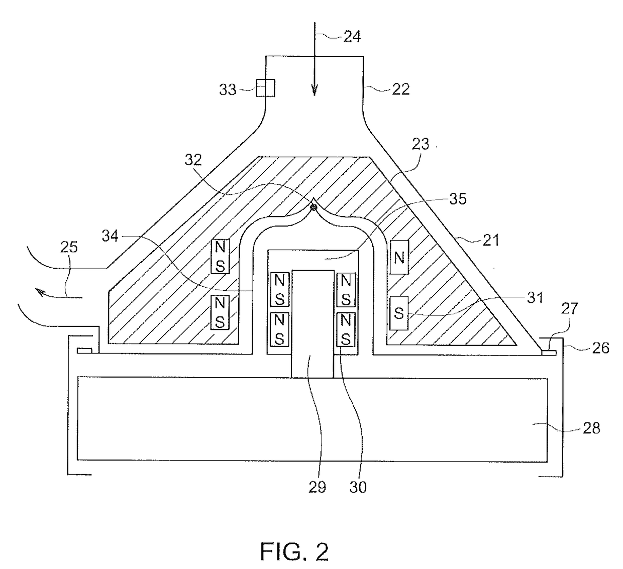
[0139]the present invention is depicted in FIG. 8, wherein a further impeller 81 has been mounted or positioned within the blood housing. The impeller 81 preferably includes at least three blades joined about a central hub. This embodiment functions in a similar manner to the blood pump in FIG. 2, wherein the elongated pivot member 29 extends in the pump housing and magnetically induces rotation of the impeller through the cooperation the first and second sets of permanent magnets.

[0140]The impeller 81 is generally conical shape wherein the blades extend radially from the hub.

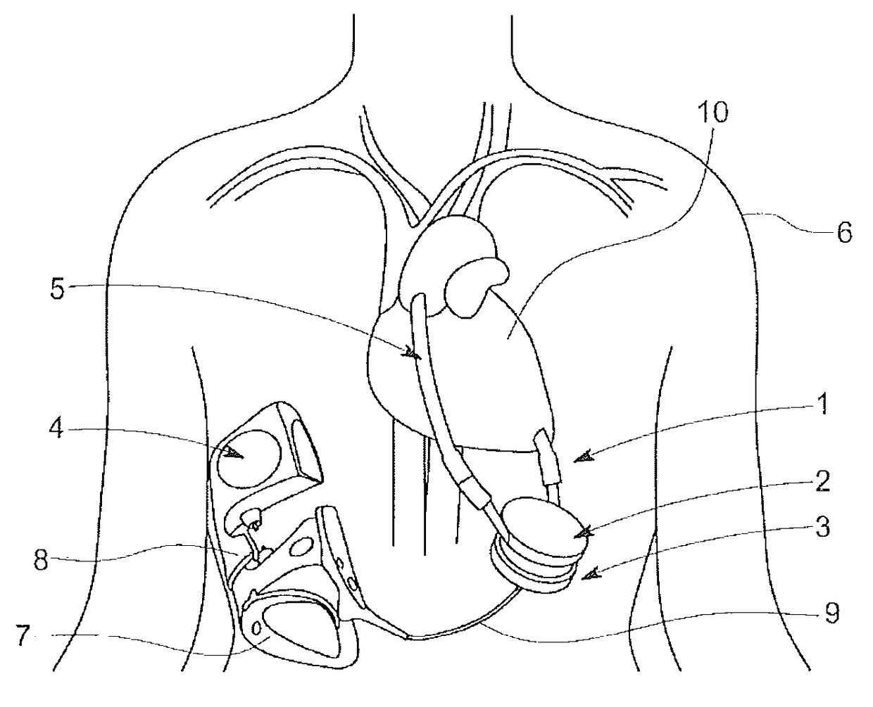
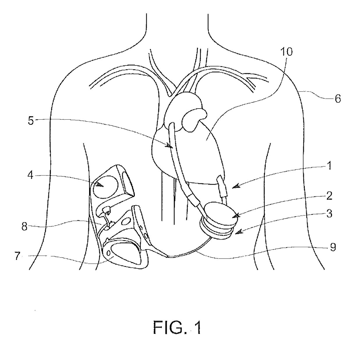
[0141]The system shown in FIG. 9 depicts an alternate embodiment to that shown in FIG. 1. This present preferred embodiment the controller 4 and battery 4 have been replaced with a controller bag 91. The controller bag 91 preferably includes a controller with an internal rechargeable battery and an external rechargeable battery. The bag 91 is adapted to be portable and carried by the patient holding the strap 9...


PUM


Abstract

A blood pump device comprising: a centrifugal blood pump having: a pump housing defining an inlet to receive blood and direct blood onto an impeller, the pump housing having a top bezel and a central column directed into the middle of a cavity within the pump housing; the impeller is adapted, in use, to rotate in the cavity around the central column and to be suspended on a pivot bearing mounted between the middle of the lower surface of the impeller and the middle of the upper surface of the central column; the impeller is stabilised, in use, by the rotation of blades generating a centrifugal force acting on the blades in radial direction away from the central column.

Description

FIELD OF THE INVENTION[0001]The present invention relates to a blood pump device that may be used as a ventricular assist device being suitable for left or right sides of heart preferably adapted to be able to be manufactured at a relatively low cost. The present invention may also include a ventricular assist system.BACKGROUND OF THE INVENTION[0002]Previously, there have been many attempts to create an improved heart assist device. Specifically, many of the previous inventions in this field have focused on providing a left ventricular assist device (LVAD) which is implantable.[0003]Most of the devices and systems that have targeted the permanent implant market have focused on developing blood pumps that are suitable for beyond the general average life expectancy of the patient. This leads many implantable left ventricular assist devices (LVADs) to be over-engineered and being extremely expensive to manufacture.[0004]Many of the LVADs used for permanent implantation are manufactured...

Claims


Application Information

Patent Timeline
IPC IPC(8): A61M1/12F04D1/00F04D29/02F04D29/24F04D25/06A61M1/10F04D29/42A61M60/232A61M60/419A61M60/531A61M60/554A61M60/562A61M60/806A61M60/825
CPCA61M1/122A61M1/1012A61M1/1029F04D1/00A61M2205/02F04D29/242F04D25/06F04D29/026F04D29/426F04D29/048A61M2205/3334A61M60/419A61M60/148A61M60/554A61M60/232A61M60/562A61M60/531A61M60/806A61M60/825
Inventor BEGG, JOHNAYRE, PETERBALAKRISHNAN, KOMARAKSHI RAJAGOPALAN
Owner CARDIOBIONIC PTY LTD
Learn More