Hydrogen generation system and fuel cell system

a fuel cell and hydrogen generation technology, applied in electrochemical generators, sustainable manufacturing/processing, chemistry apparatus and processes, etc., can solve the problems of reducing the ability of the reformer to produce hydrogen-containing gas, affecting the equilibrium, and affecting so as to achieve low cost and not degrade the performance of the reformer

Inactive Publication Date: 2017-06-08
PANASONIC INTELLECTUAL PROPERTY MANAGEMENT CO LTD
View PDF4 Cites 3 Cited by
  • Summary
  • Abstract
  • Description
  • Claims
  • Application Information

AI Technical Summary

Benefits of technology

[0009]One non-limiting and exemplary embodiment provides a hydrogen generation system capable of detecti...

Problems solved by technology

In the above hydrogen generation system, an insufficient supply of the reforming water disturbs the equilibrium of the reaction conducte...

Method used


Image

  • Hydrogen generation system and fuel cell system
  • Hydrogen generation system and fuel cell system
  • Hydrogen generation system and fuel cell system

Examples


embodiment 1

Hydrogen Generation System

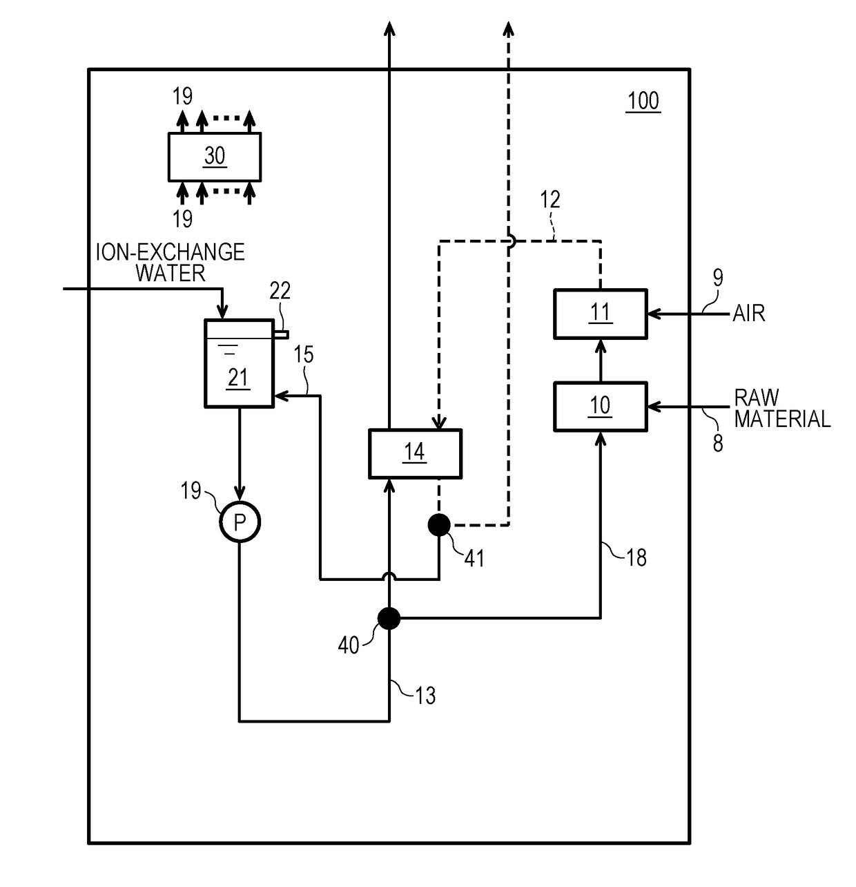
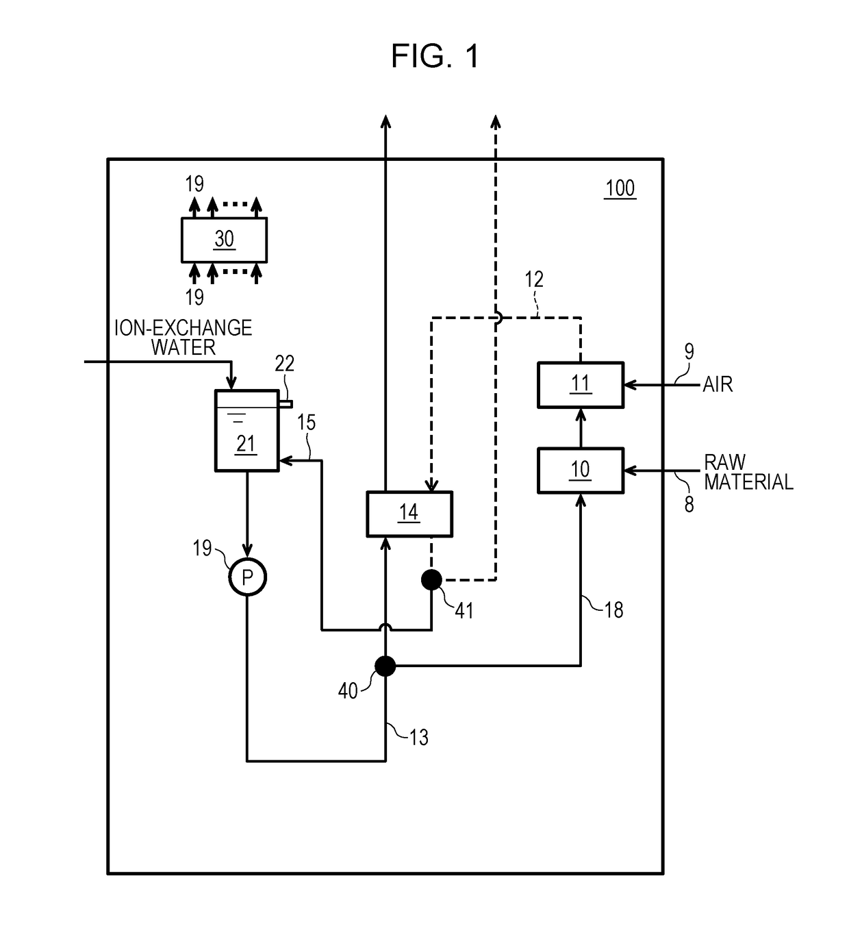
[0049]A hydrogen generation system 100 according to Embodiment 1 of the present disclosure is described below with reference to FIG. 1. FIG. 1 schematically illustrates an example of the hydrogen generation system 100 according to Embodiment 1 of the present disclosure. The hydrogen generation system 100 is a system that produces a hydrogen-containing gas from a raw material and reforming water (e.g., ion-exchange water) that are fed from external sources. As illustrated in FIG. 1, the hydrogen generation system 100 includes a raw-material-feeding path 8, an air-feeding path 9, a reformer 10, a combustor 11, an exhaust-gas path 12, a cooling-water path 13, a condenser 14, a condensed-water path 15, a reforming-water path 18, a water pump 19, a water tank 21, and a controller 30. The water tank 21 may be provided with an overflow path 22.

[0050]The reformer 10 is a reaction device that produces a hydrogen-containing gas from the raw material and the reforming...

modification example 1 of embodiment 1

[0076]A hydrogen generation system 100 according to Modification Example 1 of Embodiment 1 is described below. The hydrogen generation system 100 according to Modification Example 1 of Embodiment 1 differs from the hydrogen generation system 100 according to Embodiment 1 in the following points.

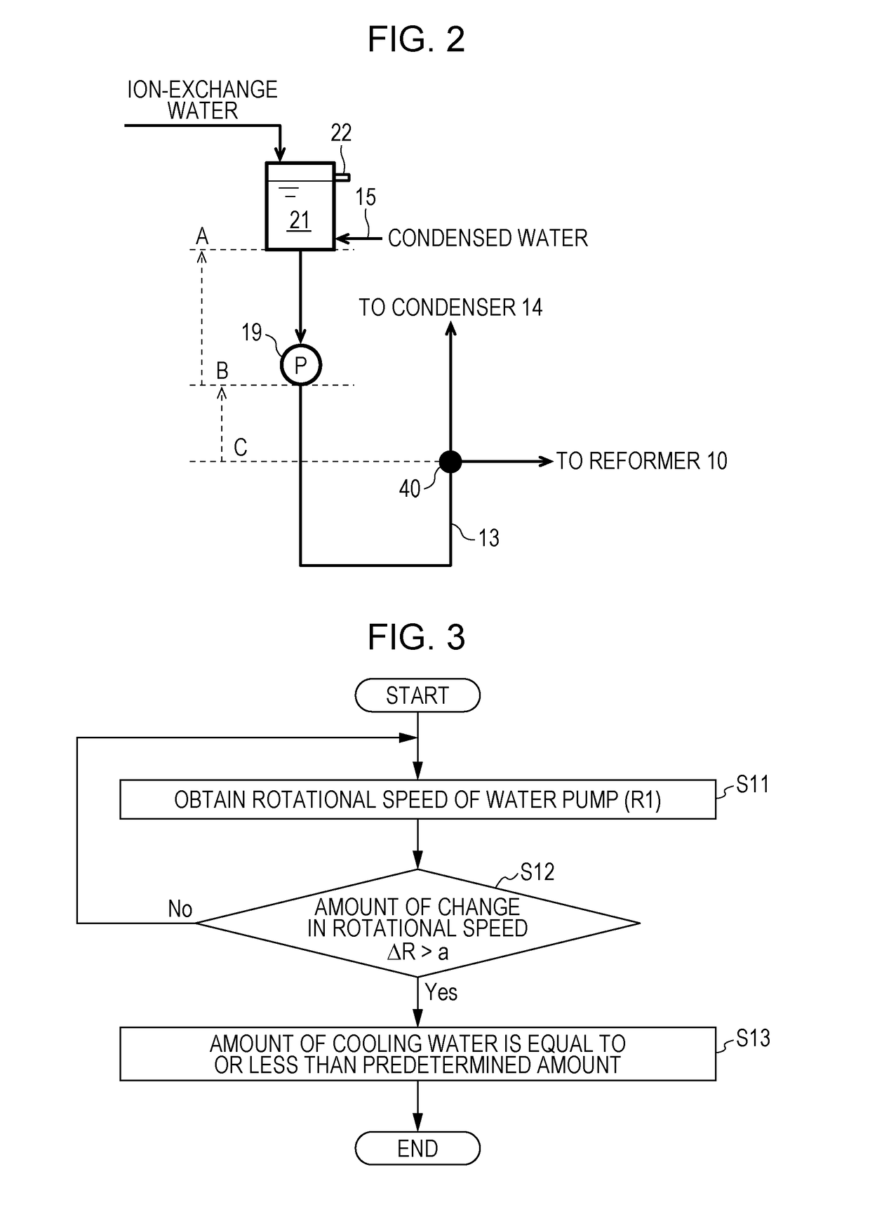
[0077]Specifically, in the hydrogen generation system 100 according to Modification Example 1 of Embodiment 1, the flow rate of the exhaust gas produced in the combustor 11 is changed depending on the flow rate of the hydrogen-containing gas produced in the reformer 10; and the flow rate of the cooling water fed by the water pump 19 is changed in accordance with the change in the amount of heat of the exhaust gas fed into the condenser 14. Since the hydrogen generation system 100 according to Modification Example 1 of Embodiment 1 is the same as the hydrogen generation system 100 according to Embodiment 1 except for the above points, the same components are denoted by the same reference numer...

modification example 2 of embodiment 1

[0082]A hydrogen generation system 200 according to Modification Example 2 of Embodiment 1 is described below with reference to FIG. 5. FIG. 5 schematically illustrates an example of the hydrogen generation system 200 according to Modification Example 2 of Embodiment 1 of the present disclosure.

[0083]The hydrogen generation system 200 according to Modification Example 2 of Embodiment 1 differs from the hydrogen generation system 100 according to Embodiment 1 in the following points. Specifically, while, in the hydrogen generation system 100 according to Embodiment 1, the cooling water is discharged to the outside of the system along the cooling-water path 13 communicated with the outside of the system and ion-exchange water is fed from the external source into the water tank 21 to be used as cooling water, in the hydrogen generation system 200 according to Modification Example 2 of Embodiment 1, the cooling-water path 13 does not extend toward the outside of the system but returns t...


PUM


Abstract

A hydrogen generation system includes a reformer that produces a hydrogen-containing gas from a raw material and reforming water, a combustor that burns the hydrogen-containing gas and air, an exhaust-gas path, a cooling-water path, a condenser that produces condensed water by exchanging heat between the exhaust gas and the cooling water, a water tank that stores the cooling water, a water pump that feeds the cooling water into the condenser, a reforming-water path along which part of the cooling water is passed into the reformer to serve as reforming water which is branched from the cooling-water path, and a controller. The water tank is disposed at a position higher than the water pump. The water pump is disposed at a position higher than the junction. The controller detects an insufficient supply of the cooling water on the basis of the rotational speed of the water pump.

Description

BACKGROUND[0001]1. Technical Field[0002]The present disclosure relates to a hydrogen generation system that produces a hydrogen-containing gas from a raw material and reforming water and a fuel cell system that includes the hydrogen generation system.[0003]2. Description of the Related Art[0004]A hydrogen generation system that includes a reformer that produces a hydrogen-containing gas by reforming a raw material such as natural gas or LPG with steam that is vaporized reforming water; a vaporizer that vaporizes the reforming water; a raw-material feeder that feeds the raw material into the reformer; a reforming-water feeder that feeds the reforming water into the vaporizer; and a water tank that stores the reforming water is known in the related art.[0005]In the above hydrogen generation system, an insufficient supply of the reforming water disturbs the equilibrium of the reaction conducted in the reformer. This causes carbonization of the raw material and reduces the ability of th...

Claims


Application Information

Patent Timeline
IPC IPC(8): H01M8/0612H01M8/04014H01M8/04029H01M8/04089
CPCH01M8/0618H01M8/0625H01M8/04029H01M8/04022H01M8/04089C01B3/38C01B2203/0233C01B2203/0244C01B2203/066C01B2203/0822C01B2203/0827C01B2203/1241C01B2203/1247C01B2203/1258C01B2203/148C01B2203/16C01B2203/169C01B3/384H01M8/04425H01M8/04776Y02E60/50Y02P20/10
Inventor MORITA, JUNJIYUKIMASA, AKINORIISHINO, HISANORI
Owner PANASONIC INTELLECTUAL PROPERTY MANAGEMENT CO LTD
Why Eureka
Try Eureka