Stator of motor and inner rotor-type motor including stator

Active Publication Date: 2017-06-08
MINEBEAMITSUMI INC
View PDF11 Cites 12 Cited by
  • Summary
  • Abstract
  • Description
  • Claims
  • Application Information

AI Technical Summary

Benefits of technology

[0022]According to the present disclosure, it is possible to provide a stator of a motor and an inner rotor-type motor including the stator that

Problems solved by technology

However, when a coil having a large diameter is used in order to feed a large current to the motor for the purpose of an increase in an output of the motor, since the thickness of a film provided on the surface of the coil increases, it is difficult to remove the film in a process for soldering the end portion o

Method used


Image

  • Stator of motor and inner rotor-type motor including stator
  • Stator of motor and inner rotor-type motor including stator
  • Stator of motor and inner rotor-type motor including stator

Examples


Embodiment Construction

[0036]A mode for carrying out the present disclosure (hereinafter referred to as “embodiment”) is explained in detail below with reference to the accompanying drawings.

[0037]Note that the same elements are denoted by the same numbers throughout the entire explanation of the embodiment.

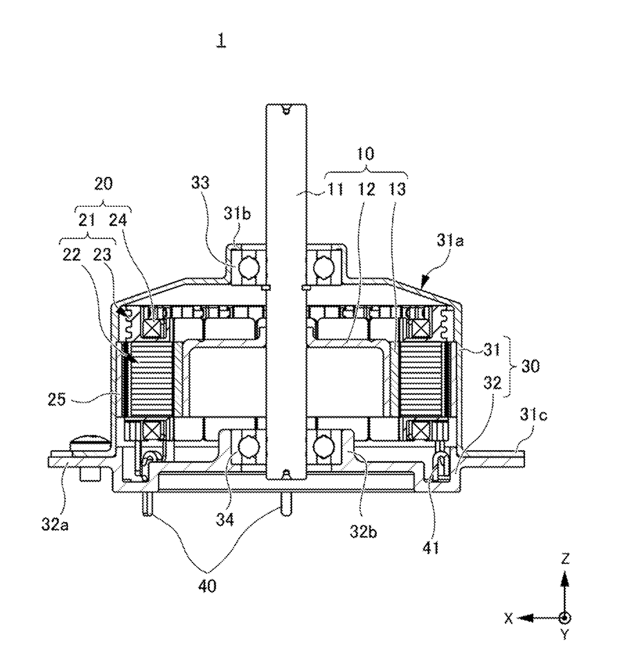
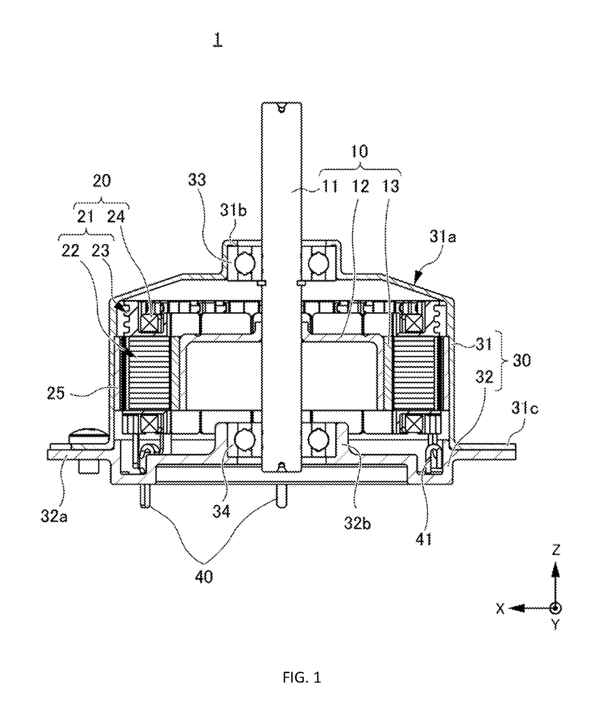
[0038]FIG. 1 is a sectional view of an inner rotor-type motor 1 (hereinafter may simply be described as motor 1) including a stator 20 in the embodiment according to the present disclosure. In the following explanation, the motor 1 is explained and the stator 20 in the embodiment according to the present disclosure is also explained.

[0039]Note that the motor 1 in this embodiment is a brushless motor but does not need to be limited to a brushless motor.

[0040]As shown in FIG. 1, the motor 1 in this embodiment includes a rotor 10, the stator 20, and a housing 30 covering the rotor 10 and the stator 20.

Rotor

[0041]The rotor 10 includes a shaft 11 functioning as a rotating shaft, a rotor yoke 12 fixed to the...


PUM


Abstract

A stator of a motor comprises a core section including a core outer circumference part forming an annular shape and a plurality of core tooth parts projecting radially inward from the core outer circumference part; an insulator covering at least an outer circumference of each of the core tooth parts and an end face in an axial direction of the core outer circumference part; a coil wound on each of the core tooth parts via the insulator; and a terminal attached to the core outer circumference part via the insulator, an end portion of the coil being connected to the terminal, wherein the terminal includes: a leg portion extending in the axial direction; a hook portion including an open end opened in the axial direction and disposed on the core outer circumference part at a position corresponding to one of the core tooth parts in a circumferential direction, the end portion of the coil being connected to the hook portion; and a coupling portion extending from the leg portion in the circumferential direction along the core outer circumference part and connected to the hook portion, the insulator includes a terminal holding portion, to which the leg portion is attached, at a position in the end face of the core outer circumference part in a position not corresponding to the core tooth parts in the circumferential direction and a position corresponding to the leg portion of the terminal, the hook portion includes: a base end portion located on an outer side in the radial direction; a side piece portion located on the inner side in the radial direction to be arranged side by side with the base end portion; and a connecting portion connecting an end portion of the base end portion and an end portion of the side piece portion located on an opposite side of the open end side and forming a closed end, and the coupling portion of the terminal is bent to locate the hook portion radially outside the core tooth parts.

Description

CROSS REFERENCE TO RELATED APPLICATIONS[0001]This application claims the benefit of Japanese Patent Application No. 2015-235409, filed on Dec. 2, 2015, which is hereby incorporated by reference in its entirety.BACKGROUND[0002]Technical Field[0003]The present disclosure relates to a stator of a motor and an inner rotor-type motor including the stator.[0004]Background Art[0005]A stator structure of a motor including a plurality of core pieces annularly arranged along the circumferential direction of the motor has been known. Each of the plurality of core pieces includes an arcuate portion having an arcuate shape and a tooth part projecting radially inward from the arcuate portion. The arcuate portion includes a contact portion provided at an end portion on the circumferential direction side of the core piece, the contact portion being in contact with the core piece adjacent thereto, and a cutout portion formed on the radially outer side of the contact portion. The cutout portion is fo...

Claims


Application Information

Patent Timeline
IPC IPC(8): H02K3/52H02K1/27H02K21/16H02K3/30H02K5/22H02K1/14H02K3/18
CPCH02K3/521H02K1/146H02K1/2706H02K21/16H02K3/30H02K5/225H02K3/18H02K3/522
Inventor KIMPARA, SHUHEI
Owner MINEBEAMITSUMI INC
Why Eureka
Try Eureka