Camera Lens Module and Manufacturing Method Thereof

a technology of lens module and manufacturing method, which is applied in the field of photographic cameras, can solve the problems of reducing the resolution of the camera module, reducing the optical quality the inability to correct the tolerance of the assembling of the lens assembly, so as to reduce the manufacturing cost increase the production efficiency and simplify the assembling steps of the camera lens module.

Active Publication Date: 2017-06-08
NINGBO SUNNY OPOTECH CO LTD
View PDF22 Cites 12 Cited by
  • Summary
  • Abstract
  • Description
  • Claims
  • Application Information

AI Technical Summary

Benefits of technology

[0009]Another advantage of the invention is to a camera lens module with one or more optical lens modules and a manufacturing method thereof, wherein the position adjustment and the calibration are completed before the final assembling of the camera lens to simplify the assembling steps of the camera lens module, to highly increase the production efficiency of the camera lens module, and to reduce the manufacturing cost of the camera lens module.
[0010]Another advantage of the invention is to a camera lens module with one or more optical lens modules and a manufacturing method thereof, wherein the calibration of the camera lens module is based on the image quality thereof to adjust the relative position of the lens barrel so as to ensure the higher product yield of the camera lens module.
[0011]Another advantage of the invention is to a camera lens module with one or more optical lens modules and a manufacturing method thereof, wherein the camera lens module comprises a plurality of optical lens modules, each comprising at least one optical lens supported in a lens barrel. The relative position of each optical lens modules is adjustable to ensure the corrected alignment of the optical lens module so as to ensure the optical quality of the camera lens module.
[0012]Another advantage of the invention is to a camera lens module and a manufacturing method thereof, wherein the calibration of the camera lens module with one or more optical lens modules is to adjust the relative positions of the optical lens modules to compensate the unavoidable tolerance of the camera lens module so as to minimize the optical defect of camera lens module and to enhance the production efficiency while being cost effective.
[0013]Another advantage of the invention is to a camera lens module with one or more optical lens modules and a manufacturing method thereof, the relative position of the optical lens module is permanently fixed once the calibration thereof is completed to minimize the assembling steps of the camera lens module while being cost effective.
[0014]Another advantage of the invention is to a camera lens module with one or more optical lens modules and a manufacturing method thereof, wherein the structural configuration of the camera lens module is compact to reduce the overall size thereof.

Problems solved by technology

Through the assembling process, assembly errors may cause the lens eccentrically or tiltedly aligned with the light sensor chip, so as to reduce the resolution of the camera module.
It is because the assembling tolerance of the lens assembly cannot be corrected once the lens barrels are assembled.
In other words, these tolerances will reduce the optical quality of the lens assembly and affect the productivity and image quality of the lens assembly.

Method used


Image

  • Camera Lens Module and Manufacturing Method Thereof
  • Camera Lens Module and Manufacturing Method Thereof
  • Camera Lens Module and Manufacturing Method Thereof

Examples


second embodiment

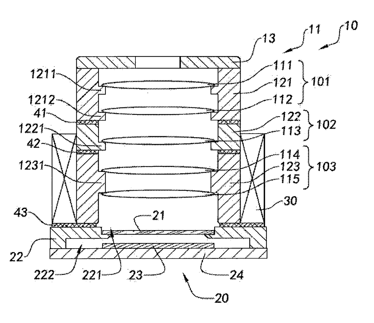
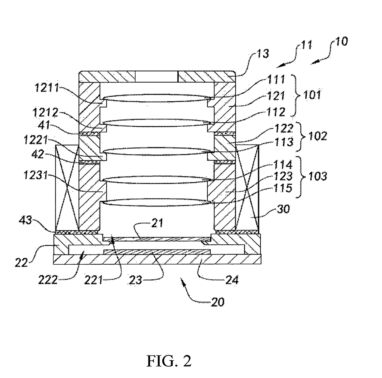
[0124] the image sensor 20A comprises a color filter 21A, a lens base 22A (i.e. the third lens barrel 123A), a photosensitive chip 23A, and a control circuit board 24A. The color filter 21A is coupled at the third lens barrel 123A at a position above the photosensitive chip 23A. In other words, the color filter 21A is provided along a photosensitive path of the photosensitive chip 23A. The photosensitive chip 23A is operatively coupled on top of the control circuit board 24A.

[0125]In particular, the third lens barrel 123A, which is configured to have a hollow structure, has a first holding groove 221A indently formed within an inner surrounding wall of the third lens barrel 123A, a second holding groove 222A indently formed within the inner surrounding wall of the third lens barrel 123A, and a third holding groove 223A indently formed within the inner surrounding wall of the third lens barrel 123A, wherein the first, second, and third holding grooves 221A, 222A, 223A are coaxially a...

third embodiment

[0140]During the assembling process of the first optical lens module 101B, the first optical lens 111B is supported within the first lens barrel 121B via a first positioning unit 1211B which is radially and inwardly extended from an inner barrel wall of the first lens barrel 121B. In particular, the first optical lens 111B is supported at the first positioning unit 1211B via the first adhering element 41B in a semi-solidified state, such that the relative position of the first optical lens 111B is adjustable within the first lens barrel 121B. the first optical lens 111B is arranged for calibration during the calibrating process. In other words, the first optical lens 111B serves as one of the optical element to be calibrated optical elements to be calibrated. In addition, the aperture member 13B is coupled on the top edge of the first lens barrel 121B to form the first optical lens module 101B during the assembling process thereof.

[0141]In particular, the first lens barrel 121B has...

fourth embodiment

[0163] the image sensor 20C comprises a color filter 21C, a lens base (i.e. the first lens barrel 123C), a photosensitive chip 23C, and a control circuit board 24C. The color filter 21C is coupled at the first lens barrel 123C at a position above the photosensitive chip 23C. In other words, the color filter 21C is provided along a photosensitive path of the photosensitive chip 23C. The photosensitive chip 23C is operatively coupled on top of the control circuit board 24C.

[0164]The third lens barrel 123C has a first holding groove 221C indently formed within an inner surrounding wall of the third lens barrel 123C, a second holding groove 222C indently formed within the inner surrounding wall of the third lens barrel 123C, and a third holding groove 223C indently formed within the inner surrounding wall of the third lens barrel 123C. The first holding groove 221C, the second holding groove 222C, and the third holding groove 223C are formed at the upper portion, mid-portion, and the lo...


PUM


Abstract

A camera lens module includes an image sensor and a lens assembly. The image sensor includes a photosensitive chip defining a photosensitive path, wherein the lens assembly is coupled to the image sensor along the photosensitive path of the photosensitive chip. The lens assembly includes at least one optical lens module and an aperture member coupled at the optical lens module, wherein the optical lens module includes a lens barrel and at least an optical lens supported within the lens barrel. A relative position of the lens assembly with respect to the image sensor is adjustable for calibration and the relative position of the optical lens module is permanently fixed after calibration.

Description

CROSS REFERENCE OF RELATED APPLICATION[0001]This is a Continuation application that claims the benefit of priority under 3 U.S.C.§119 to a non-provisional application, application Ser. No. 15 / 057,048, filed Feb. 29, 2016.NOTICE OF COPYRIGHT[0002]A portion of the disclosure of this patent document contains material which is subject to copyright protection. The copyright owner has no objection to any reproduction by anyone of the patent disclosure, as it appears in the United States Patent and Trademark Office patent files or records, but otherwise reserves all copyright rights whatsoever.BACKGROUND OF THE PRESENT INVENTION[0003]Field of Invention[0004]The present invention relates to photographic cameras, and more particularly to a camera lens module and a manufacturing method thereof.[0005]Description of Related Arts[0006]With the rapid development of mobile communication technologies, camera modules have become a standardized equipment for electronic apparatus such as smart phones,...

Claims


Application Information

Patent Timeline
Patent Type & Authority Applications(United States)
IPC IPC(8): H04N5/225G02B7/02G02B7/00G06T7/00G03B17/12
CPCH04N5/2254H04N5/2257H04N5/2253G02B7/003G02B7/021G02B7/023G06T7/0018G03B17/12H04N23/55G02B7/025H04N17/002H04N23/57H04N23/54G03B30/00G02B7/02
Inventor WANG, MINGZHUJIANG, HENGCHEN, FEIFANLIU, CHUNMEIZHAO, BOJIEGUO, NANDING, LIANG
Owner NINGBO SUNNY OPOTECH CO LTD
Why Eureka
Try Eureka