Eureka AIR delivers breakthrough ideas for toughest innovation challenges, trusted by R&D personnel around the world.

Power Plant with Steam Generation Via Turbine Extraction

Active Publication Date: 2017-06-15
GENERAL ELECTRIC CO
View PDF45 Cites 9 Cited by
  • Summary
  • Abstract
  • Description
  • Claims
  • Application Information

AI Technical Summary

Benefits of technology

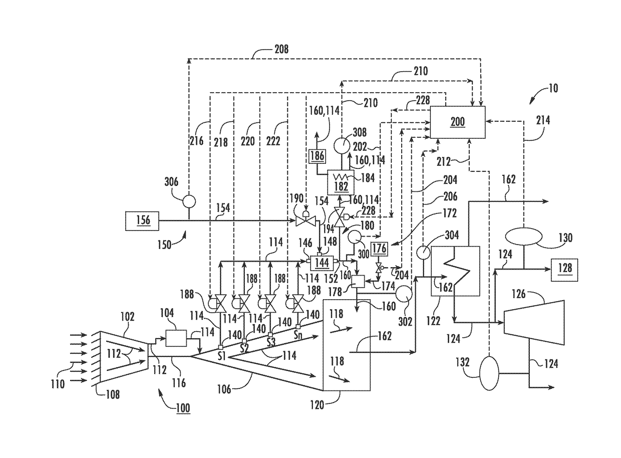
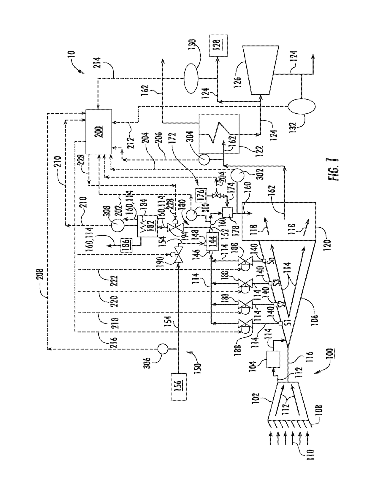
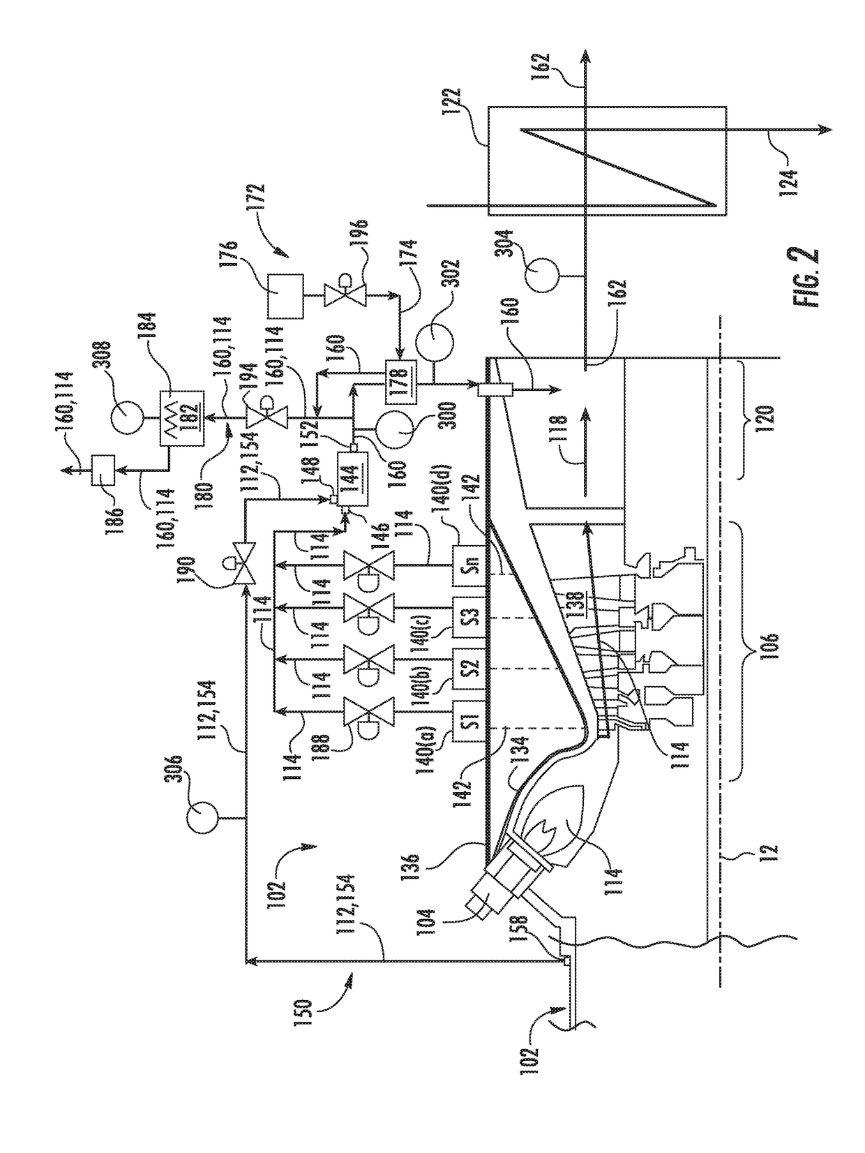
The disclosure is about a power plant that includes a gas turbine, a compressor, a combustor, and a turbine. It also has an exhaust duct and a cooling system. The cooling system provides a cooled combustion gas to the exhaust duct, which mixes with the exhaust gas to create a hot gas mixture. The hot gas mixture then flows into a heat exchanger. A gas distribution manifold distributes the combustion gas or cooled combustion gas to other operations of the power plant. The technical effect of this invention is to create a more efficient power plant that produces energy from combustion gas.

Problems solved by technology

For example, to meet power plant steam demand while maintaining acceptable emissions levels, it may be necessary to operate the gas turbine at full-speed full-load conditions, even when grid demand or power plant demand for electricity is low, thereby reducing overall power plant efficiency.

Method used


Image

  • Power Plant with Steam Generation Via Turbine Extraction
  • Power Plant with Steam Generation Via Turbine Extraction
  • Power Plant with Steam Generation Via Turbine Extraction

Examples


Embodiment Construction

[0013]Reference will now be made in detail to present embodiments of the disclosure, one or more examples of which are illustrated in the accompanying drawings. The detailed description uses numerical and letter designations to refer to features in the drawings. Like or similar designations in the drawings and description have been used to refer to like or similar parts within the disclosure. As used herein, the terms “first”, “second”, and “third” may be used interchangeably to distinguish one component from another and are not intended to signify location or importance of the individual components. The terms “upstream” and “downstream” refer to the relative direction with respect to fluid flow in a fluid pathway. For example, “upstream” refers to the direction from which the fluid flows, and “downstream” refers to the direction to which the fluid flows.

[0014]The terminology used herein is for the purpose of describing particular embodiments only and is not intended to be limiting....


PUM


Abstract

A power plant includes a gas turbine including a turbine extraction port that is in fluid communication with a hot gas path of the turbine and an exhaust duct that receives exhaust gas from the turbine outlet. The power plant further includes a first gas cooler having a primary inlet fluidly coupled to the turbine extraction port, a secondary inlet fluidly coupled to a coolant supply system and an outlet in fluid communication with the exhaust duct. The power plant further includes a gas distribution manifold that is disposed downstream from the outlet of the first gas cooler and which receives a portion of the combustion gas or a portion of the cooled combustion gas and distributes the portion of the combustion gas or a portion of the cooled combustion to one or more secondary operations of the power plant.

Description

FIELD OF THE DISCLOSURE[0001]The present disclosure generally relates to a gas turbine power plant such as a combined cycle or cogeneration power plant. More particularly, the present disclosure relates to a power plant configured for generating steam and for providing thermal energy to support one or more secondary operations.BACKGROUND OF THE DISCLOSURE[0002]A gas turbine power plant such as a combined cycle or cogeneration power plant generally includes a gas turbine having a compressor, a combustor, a turbine, a heat recovery steam generator (HRSG) that is disposed downstream from the turbine and a steam turbine in fluid communication with the HRSG. During operation, air enters the compressor via an inlet system and is progressively compressed as it is routed towards a compressor discharge or diffuser casing that at least partially surrounds the combustor. At least a portion of the compressed air is mixed with a fuel and burned within a combustion chamber defined within the comb...

Claims


Application Information

Patent Timeline
IPC IPC(8): F01K23/10F02C3/04F01K7/16
CPCF01K23/10F01K7/16F01K17/025F01K15/00F02C3/04F02C6/18F02C7/141Y02E20/14Y02E20/16Y02P80/15F02C9/18
Inventor SCIPIO, ALSTON ILFORDEKANAYAKE, SANJIKLOSINSKI, JOSEPH PHILIP
Owner GENERAL ELECTRIC CO
Why Eureka
Eureka Blog
Learn More