Micro-light-emitting diode backlight system

a technology of light-emitting diodes and backlights, which is applied in the field of direct-view display backlights incorporating light-emitting diodes, can solve the problems of difficult handling of conventional integrated circuit handling tools and small bare dies, and achieve the effects of improving manufacturing efficiency, improving light uniformity, and reducing power consumption

Active Publication Date: 2017-06-15
X DISPLAY CO TECH LTD
View PDF16 Cites 69 Cited by
  • Summary
  • Abstract
  • Description
  • Claims
  • Application Information

AI Technical Summary

Benefits of technology

[0018]The present invention provides a backlight system having improved lig...

Problems solved by technology

The bare die can be very small, for example having dimensions less than 20 mi...

Method used


Image

  • Micro-light-emitting diode backlight system
  • Micro-light-emitting diode backlight system
  • Micro-light-emitting diode backlight system

Examples


Embodiment Construction

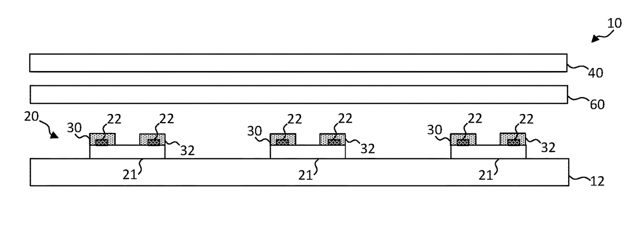
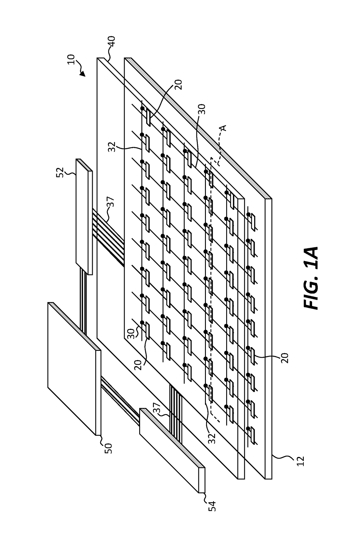
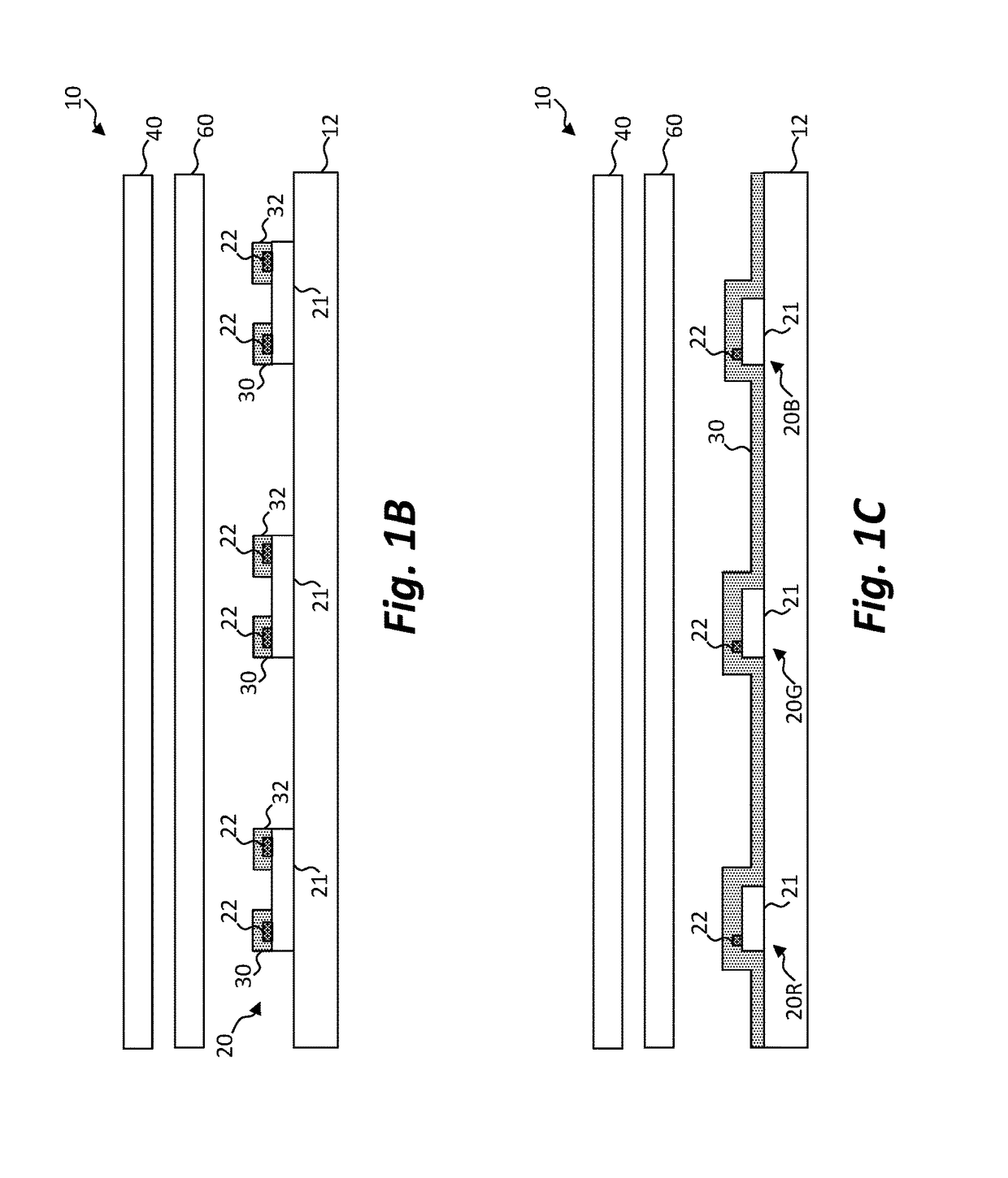
[0033]Referring to the perspectives of FIGS. 1A, 1D, and 1E and the cross sections of FIGS. 1B and 1C, in an embodiment of the present invention, a backlight system 10 includes a backplane 12 and a plurality of bare die light emitters 20 disposed over or on the backplane 12 or on or in layers on the backplane 12. Each light emitter 20 has a light-emitter substrate 21 and first and second light-emitter electrical contact pads 22 on the light-emitter substrate 21 through which electrical current is supplied to the light emitter 20 to cause the light emitter 20 to emit light (FIG. 1B). As shown in FIG. 1A, a plurality of first and second backplane conductors 30, 32 are disposed on the backplane 12 for conducting control signals to control the light emitters 20. A plurality of light valves 40 (shown as a light-valve layer 40) are disposed to receive light from the light emitters 20. In certain embodiments, the number of light valves 40 is greater than the number of light emitters 20.

[00...


PUM


Abstract

A backlight system includes a backplane and a plurality of bare die light emitters disposed on the backplane. Each light emitter has a light-emitter substrate and contact pads on the light-emitter substrate through which electrical current is supplied to cause the light emitter to emit light. A plurality of first and second backplane conductors are disposed on the backplane for conducting control signals to control the light emitters through the contact pads. A plurality of light valves is disposed to receive light from the light emitters. The number of light valves is greater than the number of light emitters.

Description

FIELD OF THE INVENTION[0001]The present invention relates to display backlights and, more particularly, to direct-view display backlights incorporating light-emitting diodes.BACKGROUND OF THE INVENTION[0002]Flat-panel displays are widely used in conjunction with computing devices, in portable devices, and for entertainment devices such as televisions. Such displays typically employ a plurality of pixels distributed over a display substrate to display images, graphics, or text. For example, liquid crystal displays (LCDs) employ liquid crystals to block or transmit light from a backlight behind the liquid crystals and organic light-emitting diode (OLED) displays rely on passing current through a layer of organic material that glows in response to the electrical current. Inorganic light-emitting diodes (LEDs) are also used in displays.[0003]Backlight systems can take a variety of forms. Direct-view backlights employ an array of light emitters located in layer behind a layer of light va...

Claims


Application Information

Patent Timeline
IPC IPC(8): F21V23/00H05B33/08G09G3/22F21V19/00H05B44/00
CPCF21V23/003F21V23/001F21V19/0025H05B33/0845G09G2360/16H05B33/0857G09G3/22F21Y2115/10F21Y2113/10H05B33/0821G09G3/3426H05B45/20H05B45/10H05B45/42
Inventor COK, RONALD S.
Owner X DISPLAY CO TECH LTD
Why Eureka
Try Eureka