Ultrasonic-rotary composite atomization mechanism

a composite atomization and ultrasonic technology, applied in the direction of liquid spraying apparatus, spraying apparatus, moving spraying apparatus, etc., can solve the problems of high equipment depreciation, low efficiency, and low efficiency of ultrasonic atomization technology, so as to reduce the burden of equipment and improve productivity.

Inactive Publication Date: 2017-06-22
PRECISION MACHINERY RES & DEV CENT
View PDF0 Cites 4 Cited by
  • Summary
  • Abstract
  • Description
  • Claims
  • Application Information

AI Technical Summary

Benefits of technology

[0008]Thereby, the liquid to be atomized flows through the inlet and the entrance, passes through the material supply channel and then enters the vibration-rotation cup. The vibration member enables the vibration-rotation cup to vibrate ultrasonically, whereby the inertia force drags the liquid reciprocally to disperse the liquid. Meanwhile, the dynamic unit rotates the vibration-rotation cup at high speed to centrifugate the liquid and then atomize the liquid. The present invention uses the rotary atomization technology and the ultrasonic atomization technology simultaneously to atomize a liquid and thus achieves a synergistic atomization effect. Therefore, the present invention can improve the productivity, reduce the burden of the equipment, and satisfy the requirement in application.

Problems solved by technology

However, the ultrasonic atomization technology has a lower atomization rate and a lower productivity.
Compared with the ultrasonic atomization technology and the high-pressure atomization technology, the rotary atomization technology has an appropriate spray utilization rate but suffers from high equipment depreciation caused by high speed rotation and shorter service life of equipment.
However, the high-pressure atomization technology has a lower spray utilization rate and suffers from that the small flow channel thereof is likely to be blocked.
Because of lower spray utilization rate, the high-pressure atomization technology is unsuitable to high-price functional liquids but usually applies to cheaper liquids, such as water and ordinary paint materials.
However, the ultrasonic atomization technology is inferior in atomization rate and hard to meet the requirement in productivity.
Further, the equipment of the ultrasonic atomization technology is expensive and has a shorter service life.
Apparently, the ultrasonic atomization technology is hard to meet requirement in atomization efficiency.
However, high rotation speed leads to high depreciation and implies higher equipment cost, shorter service life and lower reliability.
Therefore, the rotary atomization technology is also hard to satisfy requirements in application.

Method used


Image

  • Ultrasonic-rotary composite atomization mechanism
  • Ultrasonic-rotary composite atomization mechanism
  • Ultrasonic-rotary composite atomization mechanism

Examples


Embodiment Construction

[0013]The technical contents of the present invention will be described in detail in cooperation with drawings below.

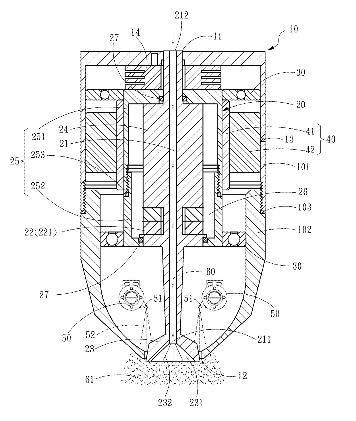
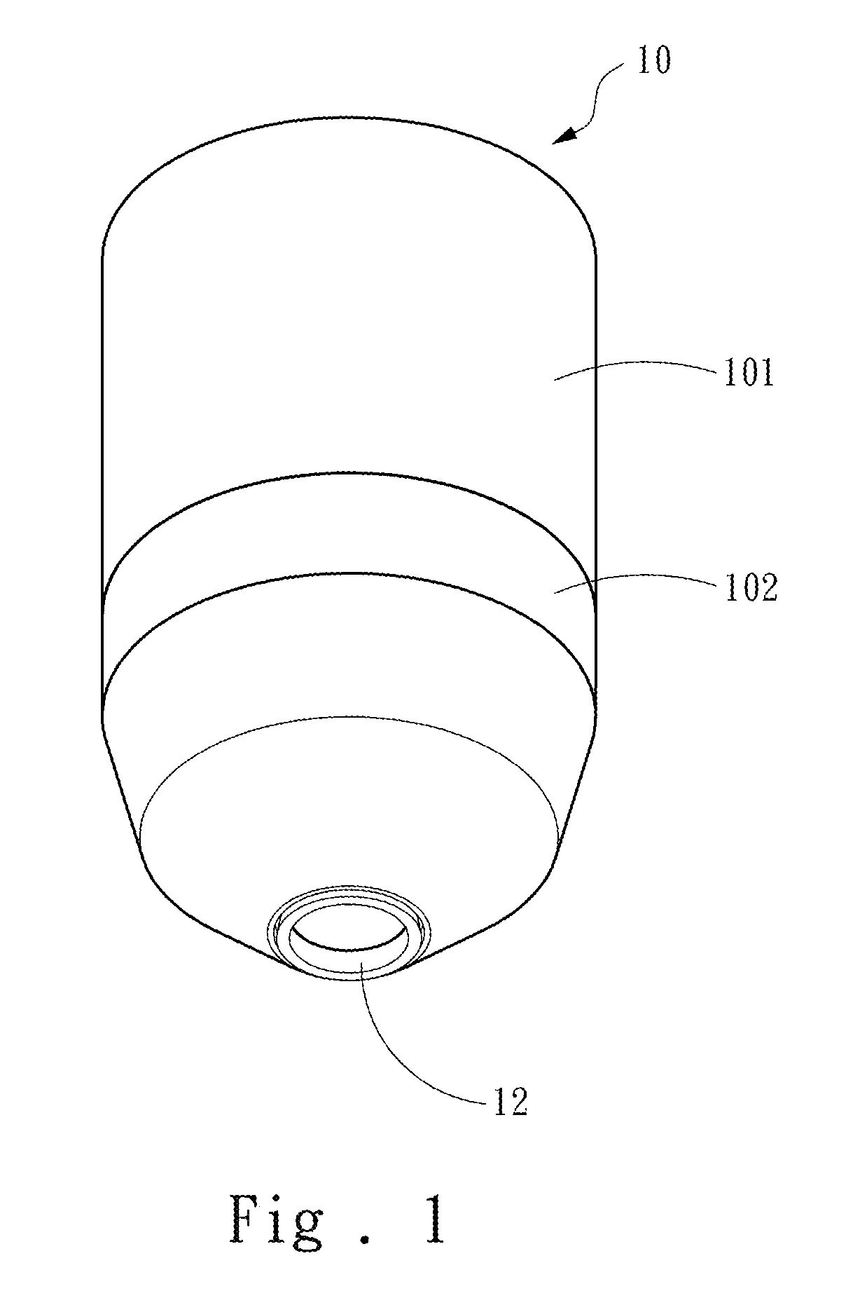
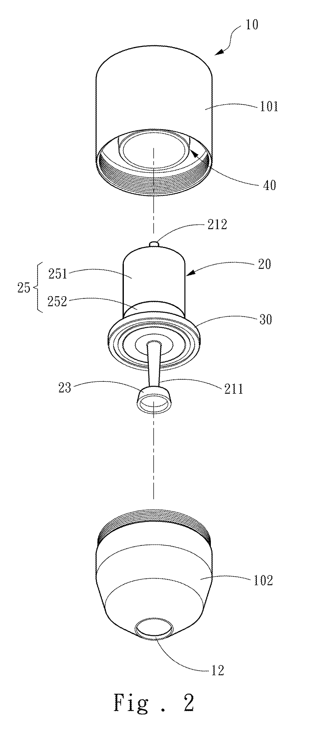
[0014]Refer to FIGS. 1-3. The present invention proposes an ultrasonic-rotary composite atomization mechanism, which comprises a housing 10 and an ultrasonic unit 20 passing through the housing 10 and free to rotate with respect to the housing 10. The housing 10 includes an inlet 11 and an outlet 12. The housing 10 includes an upper housing 101 and a lower housing 102, which can be screwed together, whereby the fabrication difficulty can be decreased. A water-proof ring 103 is disposed between the upper housing 101 and the lower housing 102 to prevent humidity from entering the housing 10.

[0015]At least one ball bearing 30 is disposed between the housing 10 and the ultrasonic unit 20, whereby the ultrasonic unit 20 is free to rotate with respect to the housing 10. Considering the stability of rotation, two ball bearings 30 are respectively disposed at two ends of the ...


PUM


Abstract

An ultrasonic-rotary composite atomization mechanism comprises a housing and an ultrasonic unit passing through the housing and free to rotate with respect to the housing. A dynamic unit is installed in a position of the ultrasonic unit, which is corresponding to the housing, to drive the ultrasonic unit to rotate with respect to the housing. The ultrasonic unit includes a material supply channel, a vibration member disposed in the ultrasonic unit, and a vibration-rotation cup connected with the material supply channel. The material supply channel carries a liquid into the vibration-rotation cup. The dynamic unit and vibration member operate simultaneously to make the vibration-rotation cup rotate at high speed and vibrate ultrasonically. Thus is generated a synergistic effect: the ultrasonic vibration uses inertia force to break the cohesion and disperse the liquid, and the high-speed rotation generates centrifugal force to atomize the liquid.

Description

FIELD OF THE INVENTION[0001]The present invention relates to an atomization technology, particularly to an ultrasonic-rotary composite atomization mechanism.BACKGROUND OF THE INVENTION[0002]Atomization is to disperse liquid into suspension particles, usually applied to agriculture, lowering the environmental temperature, and spraying paint. The conventional atomization technologies include the ultrasonic atomization technology, the rotary atomization technology, and the high-pressure atomization technology. A US patent publication No. US 2009 / 0061089 disclosed an ultrasonic atomization technology, wherein ultrasonic vibration applies force to liquid along the vibration direction to generate H-shape minute ripples on the surface of the liquid. While the intensity of the sound waves is increasing, the ripples gradually rise to form tiny liquid columns. Then, singularity points appear in the tiny liquid columns. Finally, the liquid columns break at the singularity points, and the tops ...

Claims


Application Information

Patent Timeline
Patent Type & Authority Applications(United States)
IPC IPC(8): B05B17/06B05B3/10B05B3/14
CPCB05B17/0653B05B3/1014B05B3/14B05B3/1092B05B17/063
Inventor YANG, CHIN-POLIN, PEI-KUNLIU, WANG-LIN
Owner PRECISION MACHINERY RES & DEV CENT
Why Eureka
Try Eureka