
Air-conditioning device for vehicle

Active Publication Date: 2017-06-22
TOYOTA JIDOSHA KK
View PDF2 Cites 11 Cited by
  • Summary
  • Abstract
  • Description
  • Claims
  • Application Information

AI Technical Summary

Benefits of technology

The present disclosure is about a control device for an air-conditioning system for vehicles. The control device is designed to decrease the energy consumption of the system when the opening of a water valve is decreased. This is achieved by decreasing the cooling performance of the system, which results in a reduced load on the compressor and saves energy. The control device can increase the target temperature or decrease the upper limit rotational speed of the electric compressor when the opening of the water valve is decreased. This results in a decrease in energy consumption and fuel consumption of the vehicle.

Problems solved by technology

When the airflow to the heater core is blocked by the air mix damper, heat exchange between the heater core and the airflow is no longer carried out, and supply of thermal energy to the heater core by the engine coolant thus becomes unnecessary.
When the circulatory supply of the engine coolant to the heater core is stopped by closing the water valve, the thermal energy is not supplied from the engine coolant to the heater core, resulting in excessive cooling performance of the cooling device directed to the airflow flowing through the duct.
In other words, when the cooling device is operated in the state where the water valve is closed as in the case where the water valve is opened, the airflow is excessively cooled, and at the same time, energy is unnecessarily consumed by the operation of the cooling device, resulting in degradation of fuel consumption.
However, how to control the cooling device when the water valve is closed is not disclosed in Japanese Patent Application Laid-open No.
Thus, the cooling performance of the cooling device can be decreased as a result of a decrease in a circulation flow amount of the refrigerant in the cooling device.
Further, a decrease amount of the cooling performance of the cooling device preferably corresponds to a decrease amount of the opening amount of the water valve.

Method used


Image

  • Air-conditioning device for vehicle
  • Air-conditioning device for vehicle
  • Air-conditioning device for vehicle

Examples


Embodiment Construction

[0029]Now, an embodiment of the present disclosure is described in detail with reference to the accompanying drawings.

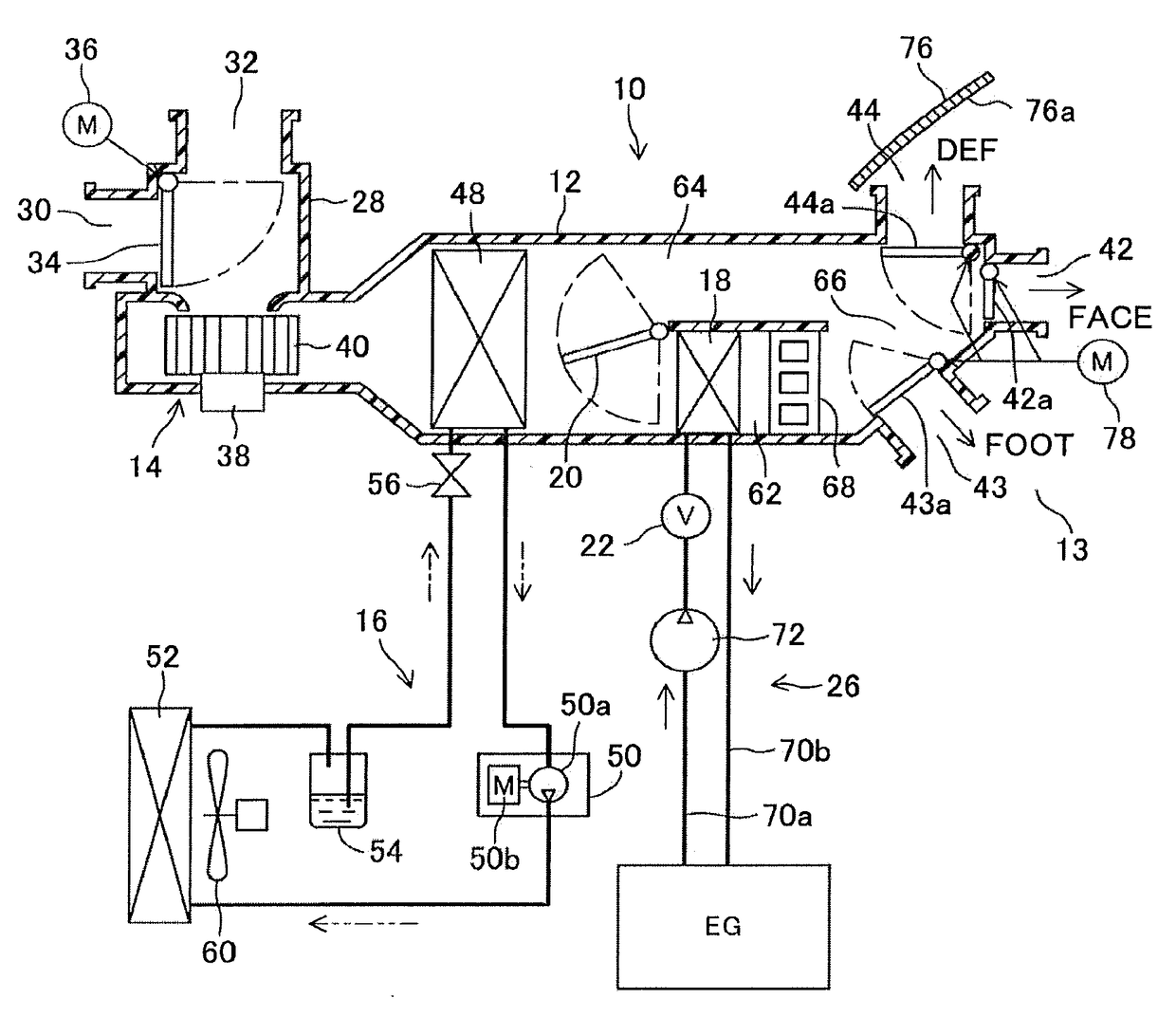
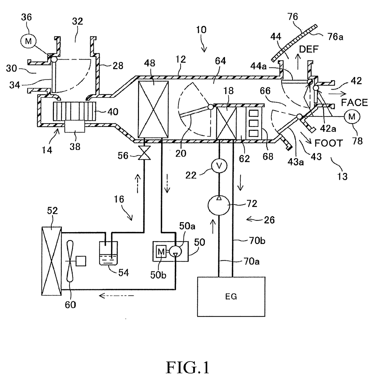
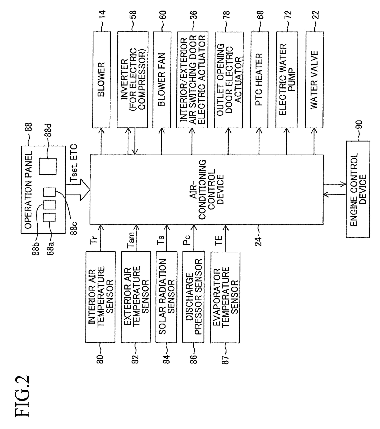
[0030]FIG. 1 is a schematic configuration diagram for illustrating a vehicle air-conditioning device 10 according to an embodiment of the present disclosure. The air-conditioning device 10 includes a duct 12 for feeding air to a vehicle cabin, a blower 14 arranged in the duct 12 for generating airflow toward the vehicle cabin 13, and a cooling device 16 for cooling the air passing through the duct 12. Further, the air-conditioning device 10 includes a heater core 18, an air mix dumper 20, a water valve 22, and an air-conditioning control device 24 (FIG. 2). The air-conditioning control device 24 is configured to control the blower 14, the cooling device 16, the air mix damper 20, the water valve 22, and the like as described later in detail.

[0031]The heater core 18 is arranged in the duct 12 on a downstream side of the airflow with respect to an evaporator 48 of the ...


PUM


Abstract

Provided is an air-conditioning device for a vehicle, including: a cooling device configured to cool air passing through a duct; a heater core, which is arranged in the duct on a downstream side of airflow with respect to the cooling device, and is configured to use an engine coolant as a heat source to heat the air; a water valve provided in a coolant circulation system on an upstream side of the heater core; and a controller configured to control those components, in which the controller is configured to decrease an opening amount of the water valve in a predetermined cooling mode. The control is configured to, when the opening amount of the water valve is decreased, decrease a rotational speed of a compressor of the cooling device, and increase a target evaporator temperature of an evaporator of the cooling device, thereby decreasing cooling performance of the cooling device.

Description

CROSS-REFERENCE TO RELATED APPLICATIONS[0001]The disclosure of Japanese Patent Application No. JP 2015-250265 filed on Dec. 22, 2015 is incorporated herein by reference in its entirety.BACKGROUND[0002]1. Technical Field[0003]The present disclosure relates to an air-conditioning device for a vehicle, e.g., a motor vehicle.[0004]2. Description of the Related Art[0005]The air-conditioning device for a vehicle includes a duct for feeding air to a vehicle cabin, a blower arranged in the duct for generating airflow toward a vehicle cabin, and a cooling device for cooling the air passing through the duct. Further, the air-conditioning device includes a heater core, an air mix dumper, a water valve, and an air-conditioning control device. The air-conditioning control device is configured to control the cooling device, the air-mix damper, the water valve, and the like.[0006]The heater core is arranged in the duct on a downstream side of the airflow with respect to an evaporator of the coolin...

Claims


Application Information

Patent Timeline
IPC IPC(8): B60H1/00B60H1/32B60H1/12
CPCB60H1/00885B60H1/12B60H1/00064B60H1/00807B60H1/3204B60H1/00814B60H1/3205B60H1/0075B60H1/00792B60H1/00828B60H1/00842B60H1/00849B60H1/00864B60H1/00964B60H1/034B60H1/04B60H1/3208B60H2001/3272B60H2001/3283B60H2001/3292
Inventor SHIMAUCHI, TAKAYUKI
Owner TOYOTA JIDOSHA KK
Learn More