Concealed structural post fastening device and method

a technology of structural post and fastening device, which is applied in the direction of fencing, construction, buildings types, etc., can solve the problems of inherent differences in the critical performance objectives of lateral load versus compression anchoring devi

Active Publication Date: 2017-06-22
BERGMAN RICHARD
View PDF19 Cites 20 Cited by
  • Summary
  • Abstract
  • Description
  • Claims
  • Application Information

AI Technical Summary

Benefits of technology

[0057]In some embodiments, the device may further comprise one or more threaded levelling holes passing through the base from the top surface to the bottom surface and being adjacent an edge of the base, and a set-screw within the one or more levelling holes being flush or below the upper surface and operable to act against the construction surface to raise or lower the base relative to the construction surface to effect tilting of the rod.
[0058]In some embodiments, a levelling plate may be provided for placement between the base and the construction surface to provide a rigid surface upon which the set-screw of the one or more leveling holes may operate.

Problems solved by technology

Of course, those experienced in the art will know that there are inherent differences in the critical performance objectives of lateral load versus compression anchoring devices.

Method used


Image

  • Concealed structural post fastening device and method
  • Concealed structural post fastening device and method
  • Concealed structural post fastening device and method

Examples


Embodiment Construction

[0085]For the purposes of promoting an understanding of the principles of the invention reference will now be made to the exemplary embodiment illustrated in the drawings, and specific language will be used to describe the same. It will nevertheless be understood that no limitation of the scope of the invention is thereby intended. Any alterations and further modifications of the inventive features illustrated herein, and any additional applications of the principles of the invention as illustrated herein, which would occur to one skilled in the relevant art and having possession of this disclosure, are to be considered within the scope of the invention.

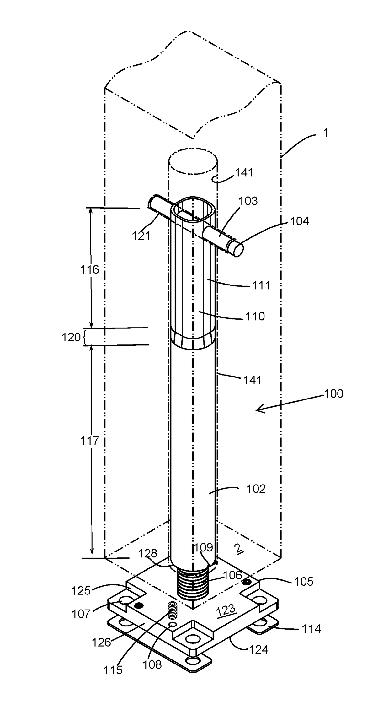
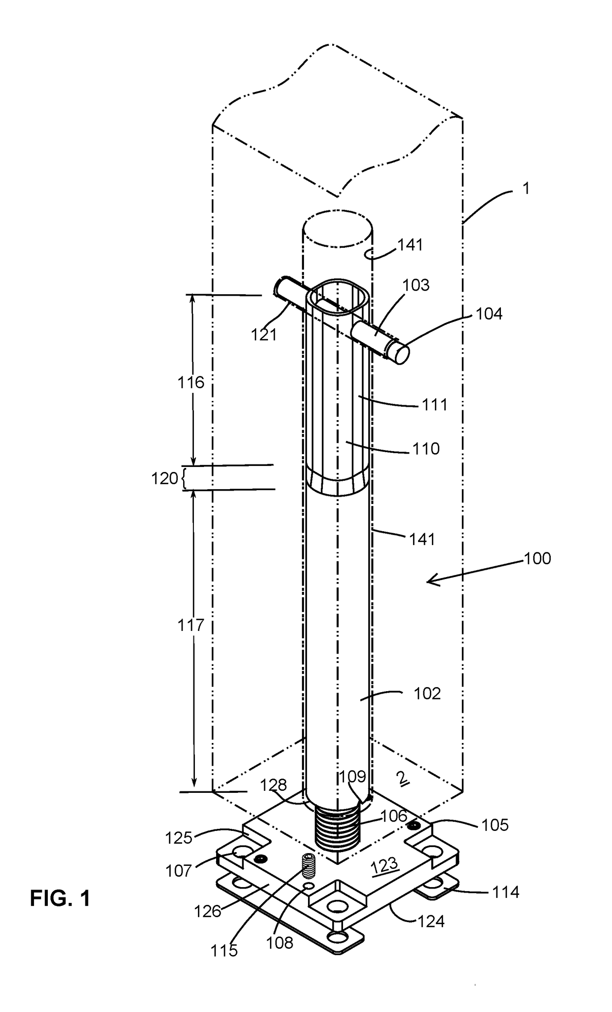
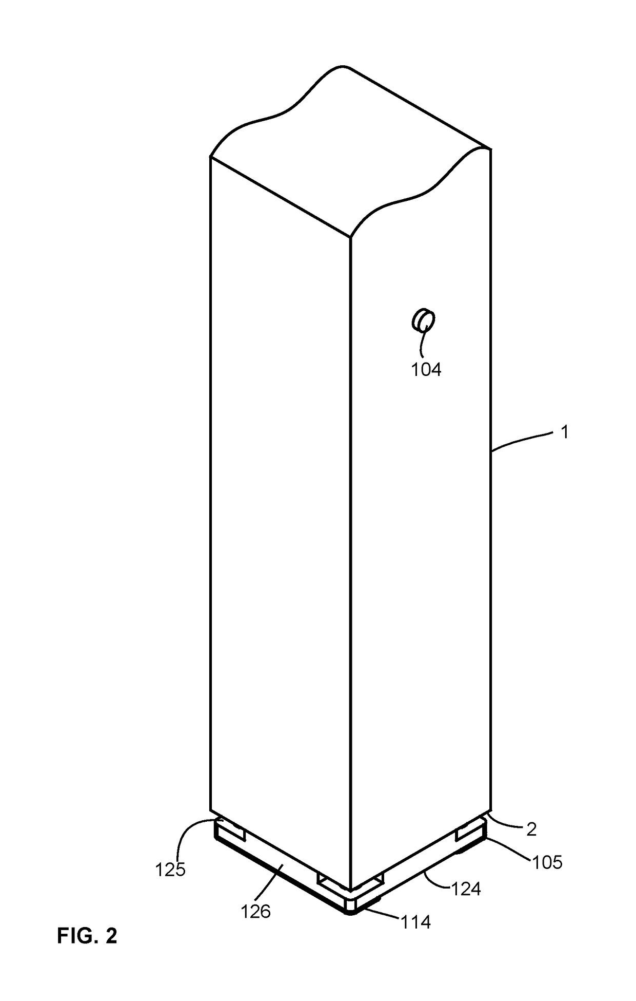
[0086]Referring to FIGS. 1-10, there is depicted an embodiment of a post fastening device 100 in accordance with the present invention. The post fastening device 100 is comprised of three major components: a base member or base 105, a tubular member or tube 102, and at least one transverse locking pin 103. An optional surface levelin...


PUM


Abstract

A post fastening device for mounting a post to a construction surface, the device comprising a base having a planar top surface and a threaded rod extending from the top surface, a tubular member for insertion into a longitudinal axial bore on the bottom end of the post, the tubular member having an upper end and a lower end with internal threads complementary to the threads of the rod, and a dowel rod for insertion into a transverse bore extending through a portion of the post and the tubular member when the tubular member is in the longitudinal bore, the dowel rod being sized to pass through the tubular member and a portion of the post on both sides of the tubular member.

Description

BACKGROUND OF THE INVENTION[0001]Field of Invention[0002]The present invention relates to devices and methods of securing solid wood, fibrous or synthetic composite posts to mounting surfaces like wood, concrete, stone or other surfaces, in a manner that the entire connecting assembly is located inside the core of the post and its base is entirely underneath the end of the post.[0003]Description of Related Art[0004]Surface mounted solid wood posts and the like are commonly connected to their fastening or anchoring assemblies by way of screws driven through a flat plate and into the bottom of the post. These devices ultimately fail when the load imposed on the post exceeds the holding power of the screw threads in the post material or when the post splits and breaks apart. A common alternative style is a bracket-like device that the end of the post is fitted into. The device surrounds the post and cradles it. These devices tend to prevent a post from splitting apart but are highly vi...

Claims


Application Information

Patent Timeline
Patent Type & Authority Applications(United States)
IPC IPC(8): E04B1/48E04F11/18E04B1/58
CPCE04B1/486E04B2001/5862E04F11/1812E04B1/5831E04B2001/268Y10T403/75E04H17/22
Inventor BERGMAN, RICHARD
Owner BERGMAN RICHARD
Why Eureka
Try Eureka