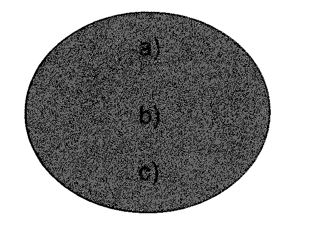
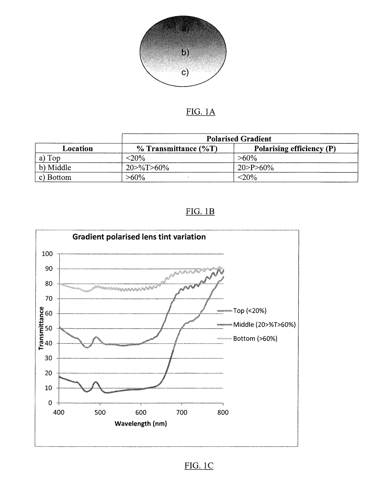
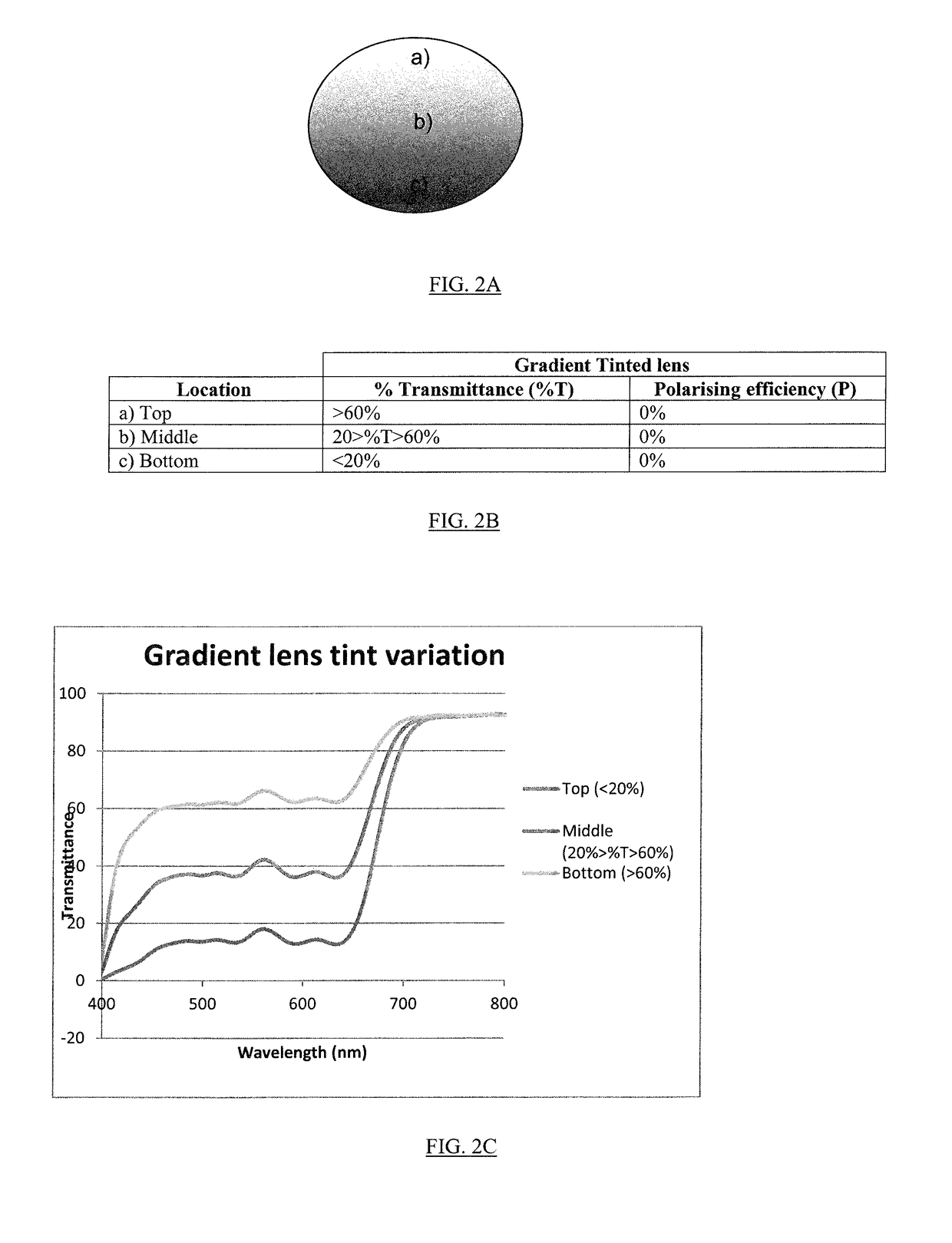
Gradient polarized ophthalmic lens
a polarized ophthalmology and lens technology, applied in the field of ophthalmology, can solve the problems of reducing visibility, affecting the ability to function as sunglasses, affecting the effect of polarization, etc., and achieve the effect of reducing polarization
- Summary
- Abstract
- Description
- Claims
- Application Information
AI Technical Summary
Benefits of technology
Problems solved by technology
Method used
Image
Examples
example 1
Plano Sunglass Lenses
[0041]A gradient polarized film is produced according to the inkjet printing method described in Trapani et al above. Discs are cut from the film, with the middle of the gradient aligned with notches in a known manner. Discs are bent under the action of heat and pressure to the same curve as the desired lens, and the bent discs are then sandwiched between two glass molds and held at a fixed distance from the front mold by a suitably configured gasket. The spacing between the glass molds is typically 1.8 to 2.2 mm in order to produce a lens suitable for sunglasses with no optical correction.
[0042]The sandwiched assembly is then filled with a catalyzed allyl diglycol carbonate monomer and cured over a period of 7 to 21 hours using practices known to those skilled in plastic lens production. After the cure is completed, the lens is removed from the assembly ready to be tinted.
[0043]The lens is aligned in a tinting rack and placed in a tinting bath, formulated to pr...
example 2
Semi-Finished Blank and Lens with Corrective Power
[0045]A gradient polarized film is produced according to the inkjet printing method described in Trapani et al above. Discs are cut from the film with the middle of the gradient aligned with notches in the normal manner. Discs are bent under the action of heat and pressure to the same curve as the desired lens to form a wafer. Bent wafer is then sandwiched between two glass molds and held at a fixed distance from the front mold (desirably <1 mm) in a suitably configured gasket.
[0046]The front and back mold of the assembly are arranged to give front surface curve and lens thickness suitable for a desired lens blank, lens blanks being commonly used to produce ophthalmic lenses with corrective power.
[0047]The sandwiched assembly is then filled with initiated allyl diglycol monomer and cured using known techniques. After curing, a semi-finished lens is removed from the sandwich and postcured. Postcuring times and temperatures are designe...
example 3
Hi-Refractive Index Lens with Corrective Power
[0050]A gradient polarized film is produced according to the inkjet printing method described above in Trapani et al. Discs are cut from the film with the middle of the gradient aligned with notches as is common practice. Discs are bent under the action of heat, pressure and humidity to the same curve as a desired lens to form a wafer. The bent wafer is then sandwiched between two glass molds and held at a fixed distance from the front mold with a suitably configured gasket. The front and back mold of the assembly are arranged to give a curve and thickness suitable for a semi-finished lens blank.
[0051]Catalyzed urethane lens monomer is then filled into the mold cavity to encase the polarized film. Urethane lens monomers are known to those skilled in the art of hi-index lens manufacture and include, but are not limited to: thiourethane lens monomer components such as xylylene diisocyanate (XDI), norbornane diisocyanate (NBDI), 2,3 Bis[(2-...
PUM
| Property | Measurement | Unit |
|---|---|---|
| distance | aaaaa | aaaaa |
| light transmission | aaaaa | aaaaa |
| corrective power | aaaaa | aaaaa |
Abstract
Description
Claims
Application Information
 - R&D
- Intellectual Property
- Life Sciences
- Materials
- Tech Scout
- Unparalleled Data Quality
- Higher Quality Content
- 60% Fewer Hallucinations
Browse by: Latest US Patents, China's latest patents, Technical Efficacy Thesaurus, Application Domain, Technology Topic, Popular Technical Reports.
© 2025 PatSnap. All rights reserved.Legal|Privacy policy|Modern Slavery Act Transparency Statement|Sitemap|About US| Contact US: help@patsnap.com


