Method and apparatus for identifying structural elements of a projected structural pattern in camera images

a technology of projected structural patterns and methods, applied in the field of method and apparatus for identifying structural elements of projected structural patterns in camera images, can solve problems such as dangerous situations, erroneous determination of distance from an object within the scene, and measurement errors, and achieve the effects of facilitating specialization, simplifying geometric ratios, and advantageously further advantageous storage capacity and computational power

Active Publication Date: 2017-06-22
PILZ (COMPANY)
View PDF0 Cites 8 Cited by
  • Summary
  • Abstract
  • Description
  • Claims
  • Application Information

AI Technical Summary

Benefits of technology

[0050]The method according to the invention can be realized particularly easily if, according to one preferred embodiment of the apparatus, the entrance pupil of the first camera, the entrance pupil of the at least one second camera, and the exit pupil of the projector are located in one plane.
[0051]In this embodiment, the geometric ratios are simplified both in the calibration and in the identification of images of structural elements. The distances of the structural elements among one another in the images of the cameras are in this arrangement independent of the distance of the projected structural elements from the cameras, i.e. always the same. An assignment of the structural elements in the calibration images is therefore easily possible. A straight line running through the two positions of a structural element in the at least two calibration images corresponds exactly to the illumination epipolar line for this structural element. Furthermore, all first illumination epipolar lines are parallel to one another, that is to say they have the same gradient and differ merely in terms of their points of intersection with the first reference axis, and all second illumination epipolar lines are parallel with respect to one another, that is to say also have the same gradient and differ merely in terms of their points of intersection with the second reference axis. The range of calibration data and thus necessary storage capacity and computational power is hereby advantageously further reduced.
[0052]A further way for helping to simplify the method according to the invention is to arrange an optical axis of the first camera, an optical axis of the at least one second camera, and an optical axis of the projector such that they are parallel with respect to one another.
[0053]In this embodiment, the camera epipolar lines of the at least two cameras are parallel with respect to one another and to straight connecting lines of the cameras. They can even be aligned with one another from camera to camera. The scanning lines of the at least two cameras can furthermore be advantageously placed to be parallel or perpendicular to the camera epipolar lines, and the distortion of the camera lenses or of the common camera lens can be easily corrected.

Problems solved by technology

During the stereoscopic evaluation of image pairs of a stereo camera, measurement errors can occur due to low-contrast objects or repeating structures within the monitored spatial region.
However, a problem arises when using dot patterns, in particular homogeneous dot patterns, as structural patterns in that erroneous assignments of dots in the camera images to the dots projected in the into the scene frequently occur.
An erroneous assignment of dots in the camera images to the dots projected onto the scene results in an erroneous determination of the distance from an object within the scene.
An erroneous distance measurement in turn has the effect that dangerous situations can arise if, for example, an object which is located in the danger zone is deemed by the cameras to be outside the danger zone, or of insufficient availability, for example of a machine within the danger zone, if an object is located outside the danger zone, but is deemed by the cameras to be inside the danger zone due to an erroneous distance measurement, and the machine is therefore switched off.
However, the generation of such more complex structural patterns is disadvantageous in light of the high outlay in terms of apparatus, i.e. the complexity of the projector.

Method used


Image

  • Method and apparatus for identifying structural elements of a projected structural pattern in camera images
  • Method and apparatus for identifying structural elements of a projected structural pattern in camera images
  • Method and apparatus for identifying structural elements of a projected structural pattern in camera images

Examples


Embodiment Construction

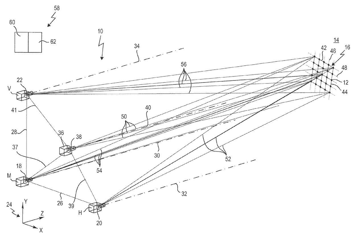
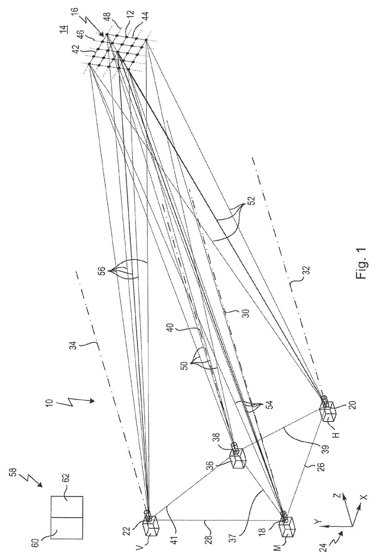
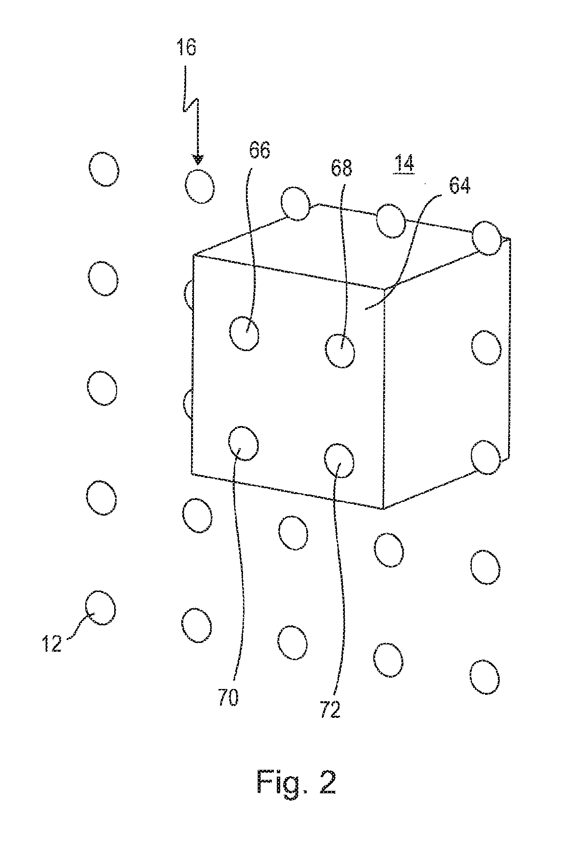
[0086]FIG. 1 shows an apparatus, which is designated with the general reference sign 10, for identifying structural elements 12 of a structural pattern 16, which is projected onto a scene 14, in camera images.

[0087]The apparatus 10 is used in particular for monitoring, in particular securing, a danger zone, in particular a danger zone of a machine (not illustrated). The scene 14 is in this case for example a three-dimensional spatial region, in which a machine, in particular a machine operating in automated fashion, such as for example a press or a robot (not illustrated), is located. Generally, moving objects, such as people, can be present in the scene 14, wherein the apparatus 10 monitors the scene 14 as to whether an object is located entirely or partially in, or approaches, the danger zone of the machine that operates in automated fashion.

[0088]The apparatus 10 has a first camera M, a second camera H and optionally, while preferred, a third camera V. The cameras M, H, and V are...


PUM


Abstract

A method for identifying in camera images individual structural elements of a structural pattern projected by a projector onto a scene. First and second cameras are used to pick up the structural pattern. The cameras are positioned at a distance from one another, and the projector is positioned outside a straight line connecting the two cameras and at a distance from the cameras. With respect to a particular structural element to be identified in the camera image of the first camera, the structural element in the camera image of the second camera which can be associated one-to-one with the particular structural element is determined by way of calibration data. The calibration data for the individual structural elements comprises combinations of parameters which correlate the respective structural element with the location and orientation of both the first camera and the projector, and of the second camera and the projector.

Description

CROSS-REFERENCES TO RELATED APPLICATIONS[0001]This application is a continuation of international patent application PCT / EP2015 / 068377, filed on August 10, 2015 designating the U.S., which international patent application has been published in German language and claims priority from German patent application No. 10 2014 113 289.7, filed on Sep. 17, 2014. The entire contents of these priority applications are incorporated herein by reference.BACKGROUND OF THE INVENTION[0002]The invention relates to a method for identifying structural elements of a structural pattern, which is projected onto a scene, in camera images.[0003]The invention furthermore relates to an apparatus for identifying structural elements of a structural pattern, which is projected onto a scene, in camera images, in particular for performing the above-mentioned method.[0004]The invention additionally relates to the use of a previously mentioned method and / or a previously mentioned apparatus for monitoring, in parti...

Claims


Application Information

Patent Timeline
Patent Type & Authority Applications(United States)
IPC IPC(8): G06T7/593G06T7/80G06T7/521H04N13/02
CPCG06T7/593H04N13/0253H04N13/0242G06T2207/30232G06T7/521G06T2207/10012G06T2207/30108G06T7/85H04N13/243H04N13/254
Inventor WENDLER, MARTIN
Owner PILZ (COMPANY)
Why Eureka
Try Eureka