
Circuit breaker with arc eliminator and power receiving/distributing equipment using same

a circuit breaker and arc eliminator technology, applied in the direction of switchgear arrangement, substation/switching arrangement details, switchgear details, etc., can solve the problems of affecting the power supply of the equipment, the device cannot be used, and the insulation function of the electric path might be lost, etc., to achieve the effect of reducing the size of the device, and reducing the power supply period

Inactive Publication Date: 2017-06-22
MITSUBISHI ELECTRIC CORP
View PDF5 Cites 3 Cited by
  • Summary
  • Abstract
  • Description
  • Claims
  • Application Information

AI Technical Summary

Benefits of technology

The technical effects of this patent text are as follows: 1. The circuit breaker with arc eliminator and power receiving / distributing equipment can be easily made smaller in size and easily planned, as there is no need to add a high-speed closing device to each electric path section inside the switchgear. 2. It is more efficient and cost-effective to replace the circuit breaker without the need for significant modification to the structure and outer dimensions of the switchgear. This reduces the equipment power stop period due to the addition modification and minimizes the running loss. 3. The replacement work can be performed by using the circuit breaker with arc eliminator that has operated when arc fault has occurred, improving workability and reducing work period. It also provides the effect of further expediting power recovery.

Problems solved by technology

However, although in very rare cases, the insulation function for the electric path might be lost due to, for example, device damage by unexpected entry of a small animal or a foreign material, insulation deterioration due to aging, great earthquake beyond the assumptions, whereby fault such as ground fault or short circuit can occur.
Even in the case where the inside of the switchgear is partitioned per electric path section by metallic shielding plates as in a metal-clad switchgear, if the fault arc continues for a long time, the range of the damaged section and the damaged switchgear expands due to deformation, melting, or the like of the metal partition wall, resulting in significant damage.
Therefore, during this period, the device in which the fault occurs is damaged to such a great extent that the device can hardly be used again, and a long period is needed for recovering the power receiving / distributing system.
During this period, power cannot be supplied.
In addition, the recovery requires huge cost.
However, in order to apply this method, it is necessary to replace the preparatory line with the arc eliminator function, and as a result, the redundancy as the power receiving / distributing equipment is deteriorated.

Method used


Image

  • Circuit breaker with arc eliminator and power receiving/distributing equipment using same
  • Circuit breaker with arc eliminator and power receiving/distributing equipment using same
  • Circuit breaker with arc eliminator and power receiving/distributing equipment using same

Examples


embodiment 1

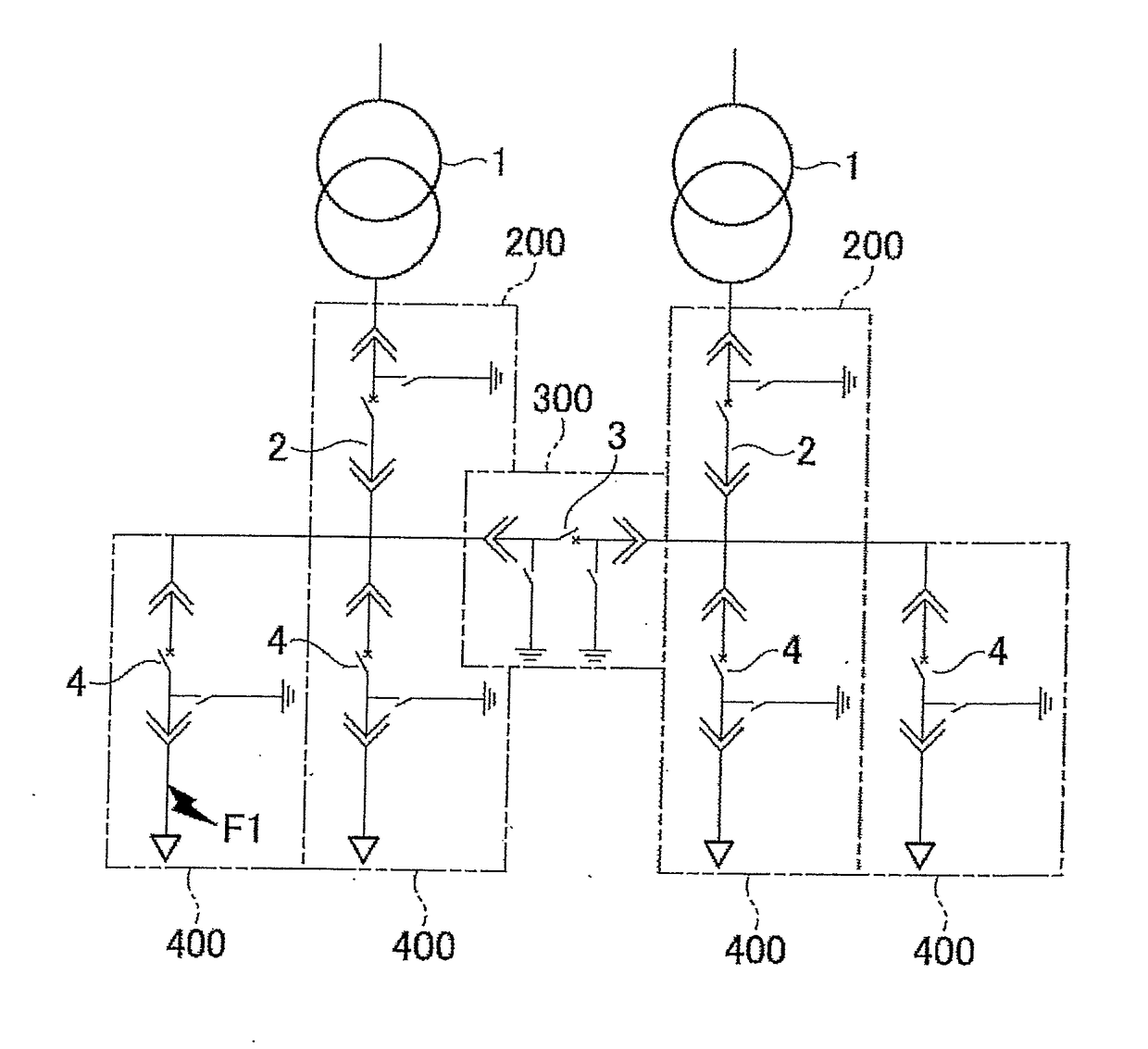
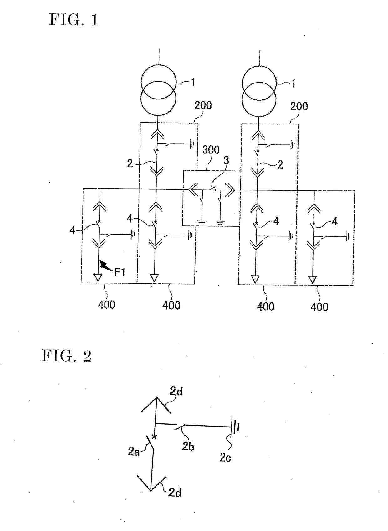
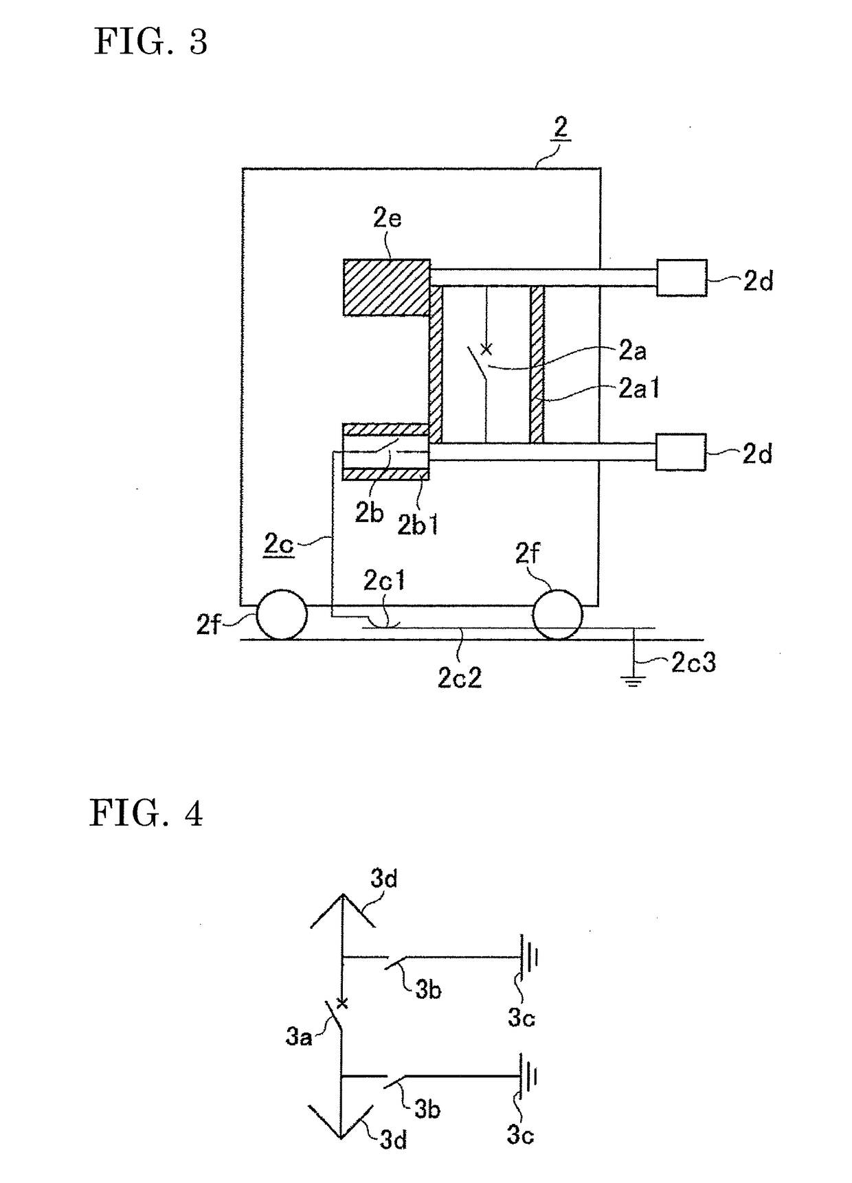
[0035]FIG. 1 is a single-line connection diagram showing an example of a circuit breaker with arc eliminator and power receiving / distributing equipment using the same, according to embodiment 1 for carrying out the present invention, and more specifically, a single-line connection diagram showing a power distribution circuit example on the secondary side of a transformer.

[0036]In FIG. 1, 2 denotes a circuit breaker with arc eliminator (one-side type) in which a high-speed closing device for arc eliminator is mounted on one side of the breaking point of the circuit breaker so that an arc eliminator can be provided on three-phase electric paths from a transformer 1 to the breaking point of the circuit breaker. 200 denotes a switchgear on which the circuit breaker 2 with arc eliminator is mounted such that the circuit breaker 2 with arc eliminator can be inserted and detached. 3 denotes a circuit breaker with arc eliminator (both-side type) in which high-speed closing devices for arc e...

embodiment 2

[0057]FIG. 6 to FIG. 10 show a circuit breaker with arc eliminator and power receiving / distributing equipment using the same, according to embodiment 2.

[0058]FIG. 6 is a single-line connection diagram showing an example of the circuit breaker with arc eliminator and the power receiving / distributing equipment using the same, according to embodiment 2 for carrying out the present invention. As shown in FIG. 7 to FIG. 10, circuit breakers 20, 30, 40 with arc eliminator according to embodiment 2 are circuit breakers with arc eliminator of a type in which the high-speed closing device is inserted, and thus are a modified type so that only the high-speed closing device portion which needs to be replaced after operation upon arc fault can be mounted and detached with respect to the circuit breaker body.

[0059]20g in FIG. 8 denotes an insertion contact portion, which forms an insertion-type contact structure in which a lower electric path 20d of the circuit breaker 20 and a high-speed closin...

embodiment 3

[0062]In the circuit breaker with arc eliminator and the power receiving / distributing equipment using the same as described in embodiment 1 and embodiment 2, the circuit breaker with arc eliminator (one-side type) and the circuit breaker with arc eliminator (both-side type) are selectively used in accordance with the electric path sections. However, all the circuit breakers may be the circuit breakers with arc eliminator (both-side type). In this case, equipment planning is further facilitated, and if the high-speed closing device at the bus portion (in FIG. 1 or FIG. 6 shown as an example, there is only one high-speed closing device for bus) has operated, another feeder circuit breaker can be used as substitute. Thus, recovery from fault is further facilitated, and an effect of shortening the power stop period in recovery is provided.

[0063]It is noted that, within the scope of the present invention, the above embodiments may be freely combined in part or whole, or each of the above...


PUM


Abstract

Power receiving / distributing equipment is composed of a switchgear incorporated for each major electric path section, wherein, when arc fault occurs on an electric path to which a circuit breaker is connected, a high-speed closing device closes to detour arc current so as to flow to a ground conductor, thereby eliminating arc at a fault electric path portion. The high-speed closing device is connected to one pole or both poles of a breaking portion of the circuit breaker, and is incorporated into an insulating support member on a corresponding pole electric path so as to be able to be drawn as a whole.

Description

TECHNICAL FIELD[0001]The present invention relates to: a circuit breaker provided with arc eliminator (fault arc elimination device) that is capable of, upon arc fault such as ground fault or short circuit caused in a low-voltage, medium-voltage, or high-voltage switchgear, swiftly grounding the electric path on which the fault occurs, so that fault current flows to the ground; and power receiving / distributing equipment using the circuit breaker provided with arc eliminator.BACKGROUND ART[0002]Low-voltage, medium-voltage, or high-voltage power receiving / distributing equipment is an equipment system essential as a social infrastructure of power supply-demand for buildings, factories, and the like, and safety and reliability thereof are sufficiently considered for, as well as the manufacturers, the overall range including installation work and operation maintenance. However, although in very rare cases, the insulation function for the electric path might be lost due to, for example, d...

Claims


Application Information

Patent Timeline
Patent Type & Authority Applications(United States)
IPC IPC(8): H02H7/22H02B11/167H02B11/28H01H79/00
CPCH02H7/222H02B11/28H02B11/167H01H79/00H02B13/025H02B1/36H02B11/02H02B13/035
Inventor NUMATA, SHINICHI
Owner MITSUBISHI ELECTRIC CORP
Learn More