Acoustic wave filter with enhanced rejection

Active Publication Date: 2017-06-22
MURATA MFG CO LTD
View PDF1 Cites 67 Cited by
  • Summary
  • Abstract
  • Description
  • Claims
  • Application Information

AI Technical Summary

Benefits of technology

[0017]In accordance with a fourth aspect of the present inventions, each of at least one of the interdigitated capacitive fingers has a length/width ratio of less than two, and preferably less than on

Problems solved by technology

In particular, such electrical filters are used to select desired electrical signal frequencies from an input signal by passing the desired signal frequencies, while blocking or attenuating other undesirable electrical signal frequencies.
This requirement for low resistance tends to drive the size and cost of the resonators for a given technology.
In most filter technologies, achieving a low insertion loss requires a c

Method used


Image

  • Acoustic wave filter with enhanced rejection
  • Acoustic wave filter with enhanced rejection
  • Acoustic wave filter with enhanced rejection

Examples


Embodiment Construction

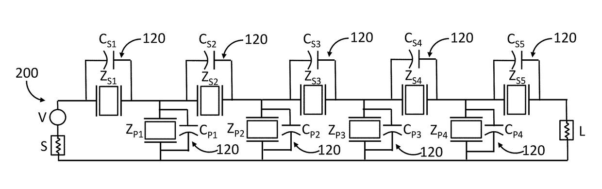
[0057]The present disclosure describes a design technique that enhances the rejection on one or both sides of a passband of an acoustic wave (AW) microwave filter, such as, e.g., a surface acoustic wave (SAW), bulk acoustic wave (BAW), film bulk acoustic resonator (FBAR), or microelectromechanical system (MEMS) filter. This technique uses standard manufacturing techniques and can be implemented without altering the overall size of the chip on which the microwave filter is disposed. This technique can be very useful when implemented in band gap contiguous duplexers. Increased rejection is also achieved in the neighboring band. Frequencies further out-of-band, both above and below the passband, can be rejected more, which will help in preventing unwanted signals interfering with the performance of the front-end receiver. Narrow band filters / duplexers can be designed, which increases the number of designs possible for a given piezoelectric material. The acoustic microwave filter may op...


PUM


Abstract

An acoustic filter comprises a piezoelectric layer, an acoustic resonator structure monolithically disposed on the piezoelectric layer, a lumped capacitive structure monolithically disposed on the piezoelectric layer and being electrically coupled to the acoustic resonator structure. The acoustic resonator structure comprises an arrangement of planar interdigitated resonator fingers, and each of the interdigitated capacitive fingers has an edge that is entirely continuous. No portion of the edge of each of the interdigitated capacitive fingers is parallel to any portions of edges of the interdigitated resonator fingers. Each of the interdigitated capacitive fingers may comprise a plurality of interdigitated capacitive sub-fingers, or each of the interdigitated capacitive fingers may have a length/width ratio of less than two.

Description

RELATED APPLICATION DATA[0001]The present application is a continuation-in-part of U.S. patent application Ser. No. 14 / 941,451, filed Nov. 13, 2015, which is expressly incorporated by reference into the present application in its entirety.FIELD OF THE INVENTION[0002]The present inventions generally relate to microwave filters, and more particularly, to acoustic wave filters designed for high frequency-selectivity applications.BACKGROUND OF THE INVENTION[0003]Electrical filters have long been used in the processing of electrical signals. In particular, such electrical filters are used to select desired electrical signal frequencies from an input signal by passing the desired signal frequencies, while blocking or attenuating other undesirable electrical signal frequencies. Filters may be classified in some general categories that include low-pass filters, high-pass filters, band-pass filters, and band-stop filters, indicative of the type of frequencies that are selectively passed by t...

Claims


Application Information

Patent Timeline
IPC IPC(8): H03H9/54H03H9/19H03H9/56
CPCH03H9/542H03H9/19H03H9/564H03H9/568H03H9/6483H03H9/64
Inventor RAIHN, KURT F.HEY-SHIPTON, GREGORY L.
Owner MURATA MFG CO LTD
Why Eureka
Try Eureka