A self-attaching fabric and methods of manufacturing same

a self-attaching fabric and fabric technology, applied in the field of fabric, can solve the problems of too coarse for medical and infant use and too thick joint area for high-fashion us

Inactive Publication Date: 2017-06-29
ENFOLD TEXTILES LTD
View PDF3 Cites 1 Cited by
  • Summary
  • Abstract
  • Description
  • Claims
  • Application Information

AI Technical Summary

Benefits of technology

[0007]It is therefore one of the objects of the present invention to obviate the disadvantages of prior art self-attachment fabrics and to provide a fabric which can be joined at any area and by avoiding thick attachment areas can be used in high fashion garments.
[0008]It is a further object of the present invention to provide a soft fabric which can be used in goods designed for use of babies.
[0009]It is a further object of the present invention to provide a soft fabric which can be used in goods designed as functional clothing for disabled populations and for maternity wearSUMMARY OF THE INVENTION

Problems solved by technology

Prior art self-adhering fabrics result in a joint area which is too thick for high fashion use and too coarse for medical and infant use.
They require sewing on of the joint materials and are limited to specific areas of the fabric.

Method used


Image

  • A self-attaching fabric and methods of manufacturing same
  • A self-attaching fabric and methods of manufacturing same
  • A self-attaching fabric and methods of manufacturing same

Examples


first embodiment

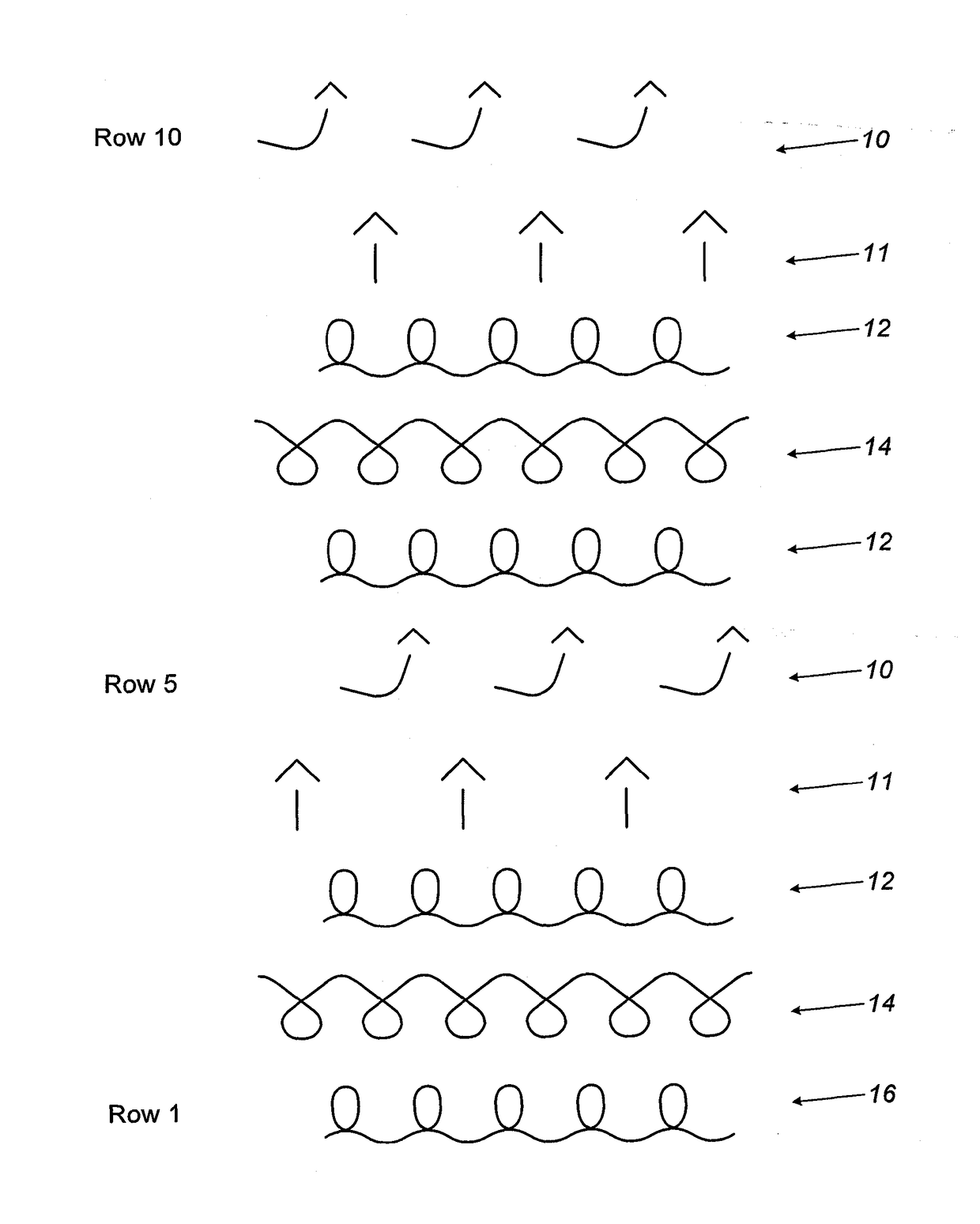
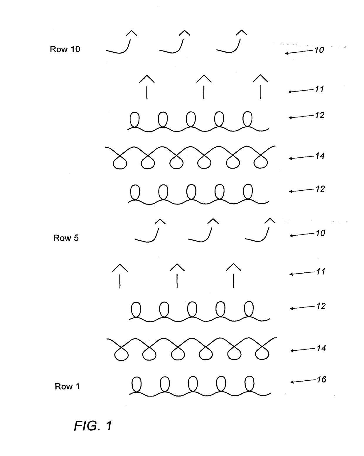
[0037]There is seen in FIG. 1 a representation of a method for manufacturing the fabric, a thin fabric provided with hooks on one side only. The diagram refers only to STEP D, which in particular serves to reveal the structure of the resulting fabric.[0038]STEP A: Providing an industrial flat knitting machine having a front needle bed and a rear needle bed and being provided with electronic controls. An example of a suitable machine is manufactured by STOLL, Germany. Typically the machines are for 12 gauge but multi-gauge machines are available from the same manufacturer.[0039]STEP B: Loading the machine with yarns as needed to form the base fabric.[0040]STEP C: Loading the machine with the monofilament yarn to form loops.

[0041]The description refers to the fabric sequence being performed on the rear needle bed, while the loops are knitted on the front bed. This arrangement can be reversed if desired.[0042]STEP D knitting the fabric including forming of the loops on one surface of t...

second embodiment

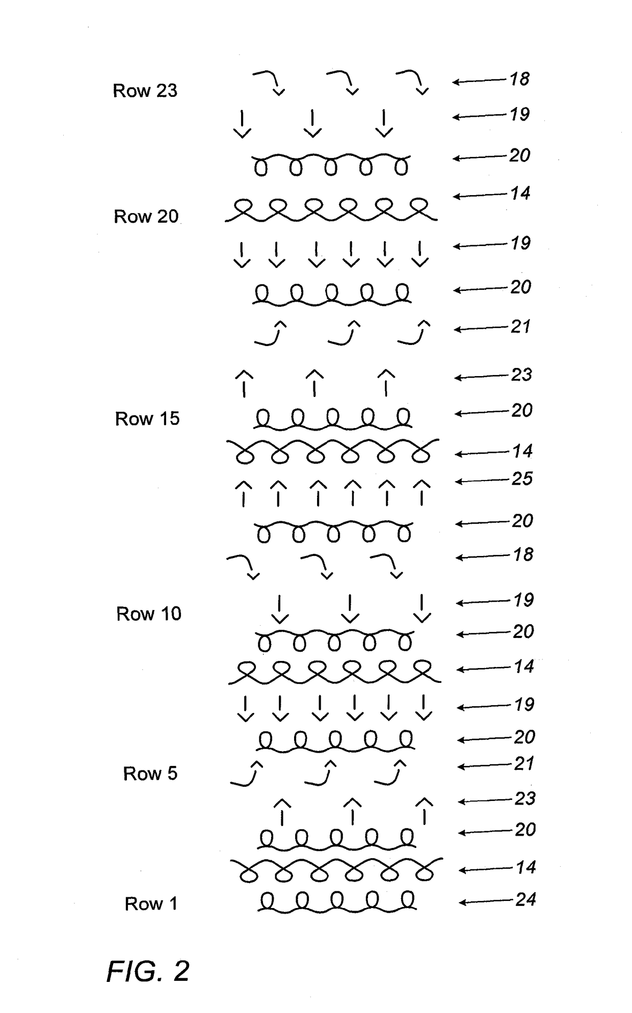
[0045]Referring now to FIG. 2, there is seen a representation of STEP D in a second embodiment wherein the fabric is provided with hooks and loops on both sides. This of course results in a fabric somewhat thicker than that described with reference to FIG. 1.

[0046]Row 1 of the diagram refers to release of alternate loops 18 from the rear needle bed (not shown). In row 2 the loops 18 are transferred 19 to the front bed (not shown).

[0047]Row 3 represents knitting of the basic yarn 22, while row 4 represents knitting the monofilament

[0048]In row 5 there is a transfer of loops 18 to the front bed, followed by knitting a row of the basic yarn 22 in row 6. Row 7 shows release 21 of loops 18 from the front bed, and their collection 23 by the rear bed is seen in row 8.

[0049]In row 9 there is a further row of knitting of the basic yarn 22, followed by knitting of the monofilament 14 in row 10.

[0050]In row 11 loops 18 of the monofilament are transferred 25 to the rear bed. In row 12 again the...


PUM

PropertyMeasurementUnit
transparentaaaaaaaaaa
pressureaaaaaaaaaa
areaaaaaaaaaaa

Abstract

The invention relates to a fabric which can attach to itself by use of hand pressure, and methods for its manufacture. The invention provides a fabric having at least part of its surface covered with small monofilament loops. The self-attaching fabric having at least part of its surface covered with small monofilament hooks which removably engage each other when the surface is pressed into contact with another similar surface to retain together the two portions of the fabric until they are separated by a peeling action.

Description

BACKGROUND OF THE INVENTION[0001]The present invention relates to a fabric which can attach to itself by use of hand pressure, and methods for its manufacture.[0002]More particularly, the invention provides a fabric having at least part of its surface covered with small monofilament hooks and loops.[0003]The best known prior art is the original Velcro patent, U.S. Pat. No. 3,009,235. Use of this product entails adding two different pads to the surfaces to be joined. Velcro is not suitable for high fashion uses because of the bulge resulting when the two pads are in contact. It is also not versatile in positioning as the surfaces can only be joined in the area covered by both pads. In U.S. Pat. No. 8,551,596 Chou discloses self-sticking fabric where the hook and loop appear on opposing sides of the fabric. The structure is a simple jersey knit and the yarns which may be used are much limited by the need to chemically dissolve part but not all of the material used as hooks.[0004]US Pa...

Claims


Application Information

Patent Timeline
Patent Type & Authority Applications(United States)
IPC IPC(8): A44B18/00D03D27/06D04B1/16D04B7/20D04B25/00D04B21/14D03D11/02
CPCA44B18/003D10B2211/04D03D27/06D03D11/02D04B7/20D04B25/00D04B1/16A44B18/0026D10B2501/0632D10B2331/04D10B2201/02D10B2201/04D10B2201/24D10B2211/02D04B21/14D04B1/02A61F13/622
Inventor KARNI, MEITAR
Owner ENFOLD TEXTILES LTD
Why Eureka
Try Eureka