Autoinjector with shock reducing elements

a technology of shock reducing elements and auto-injectors, which is applied in the direction of shock absorbers, springs/dampers, liquid based dampers, etc., can solve the problems of affecting the effect of the system

Active Publication Date: 2017-06-29
AMGEN INC
View PDF9 Cites 22 Cited by
  • Summary
  • Abstract
  • Description
  • Claims
  • Application Information

AI Technical Summary

Benefits of technology

[0010]Disclosed herein are an injection device, and methods and systems for drug delivery. Within this disclosure, reference may be made to “autoinjectors”; however, such reference should also be understood to refer to on-body injectors where the description is applicable. In various embodiments, the device may comprise a container or reservoir for storing a drug, the container comprising a stopper movably disposed in the container for expelling the drug, an injection drive mechanism comprising a plunger for acting on the stopper, and an energy source for exerting a force on the plunger to cause the plunger to act on the stopper to expel the drug, the force causing the plunger to accelerate to a velocity prior to acting on the stopper, and a damping mechanism for reducing the velocity of the plunger prior to acting on the stopper, the damping mechanism comprising a housing, a piston assembly movable in the housing and acted upon by the plunger, and a working fluid displaceable by the piston assembly for resisting movement of the plunger. The container or reservoir may contain a drug or medicament and can be a cartridge or prefilled syringe.
[0011]In various other embodiments, the device may comprise a container for storing a drug, the container comprising a stopper movably disposed in the container for expelling the drug,

Problems solved by technology

The use of springs can offer benefits of simplicity and low cost, but can have certain limitations.
To provide sufficient energy for drug delivery at the end of plunger stroke, an excessive amount of energy may be input to the system as drug delivery commences.
Further, as higher viscosity drugs are delivered via autoinjectors, the requisite spring forces will likely increase.
Because kinetic energy is proportional to velocity squared, even incremental increases in the spring constant can result in large changes in the net kinetic

Method used


Image

  • Autoinjector with shock reducing elements
  • Autoinjector with shock reducing elements
  • Autoinjector with shock reducing elements

Examples


Embodiment Construction

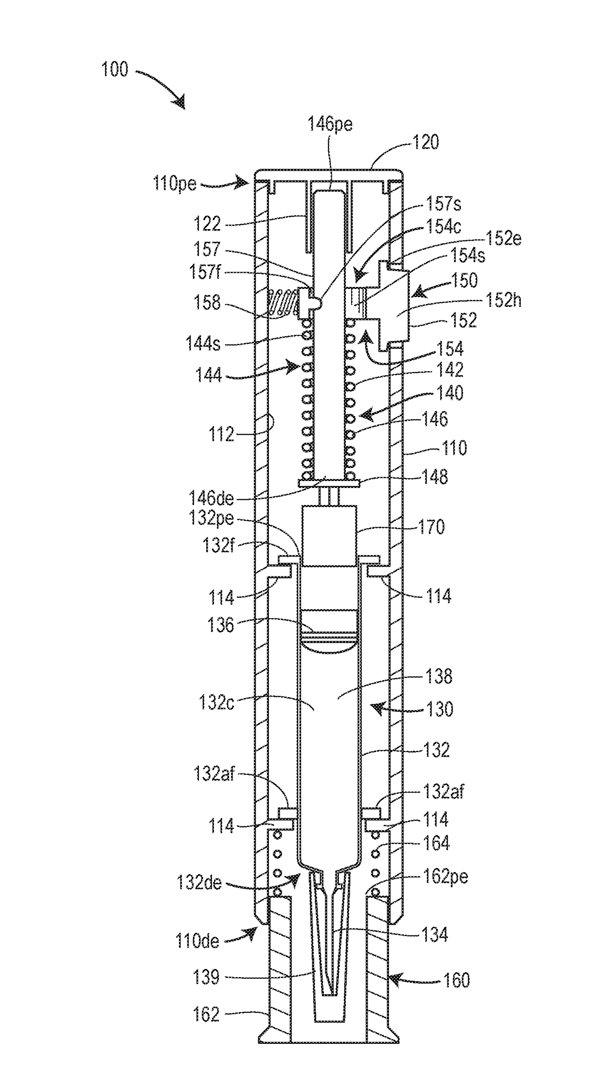
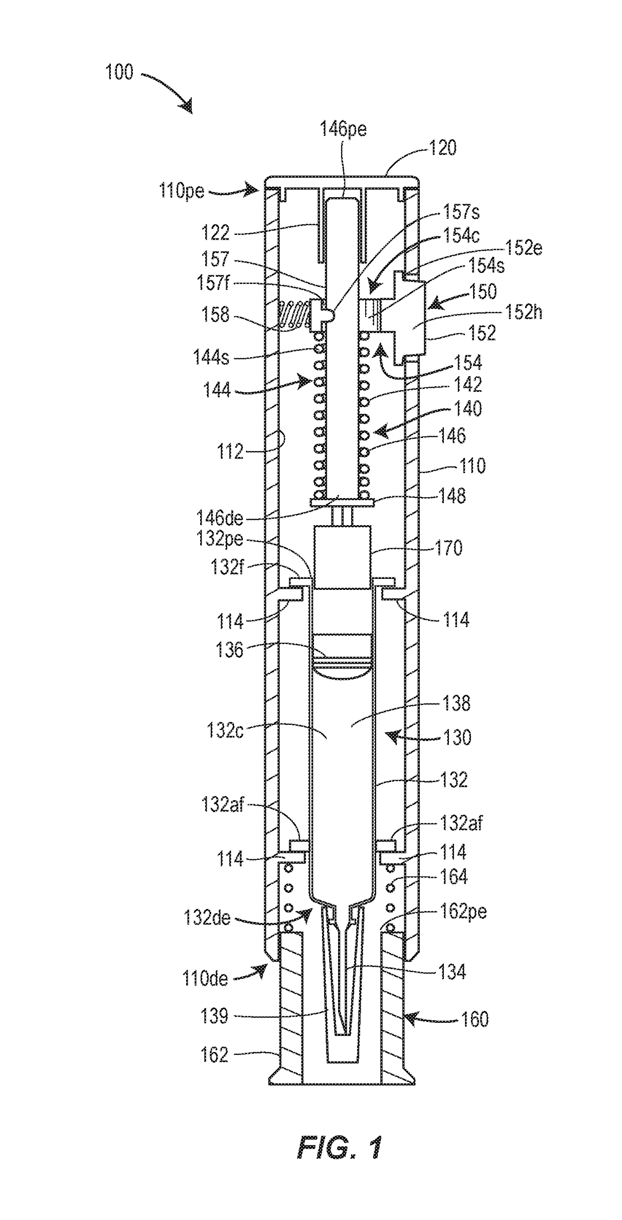
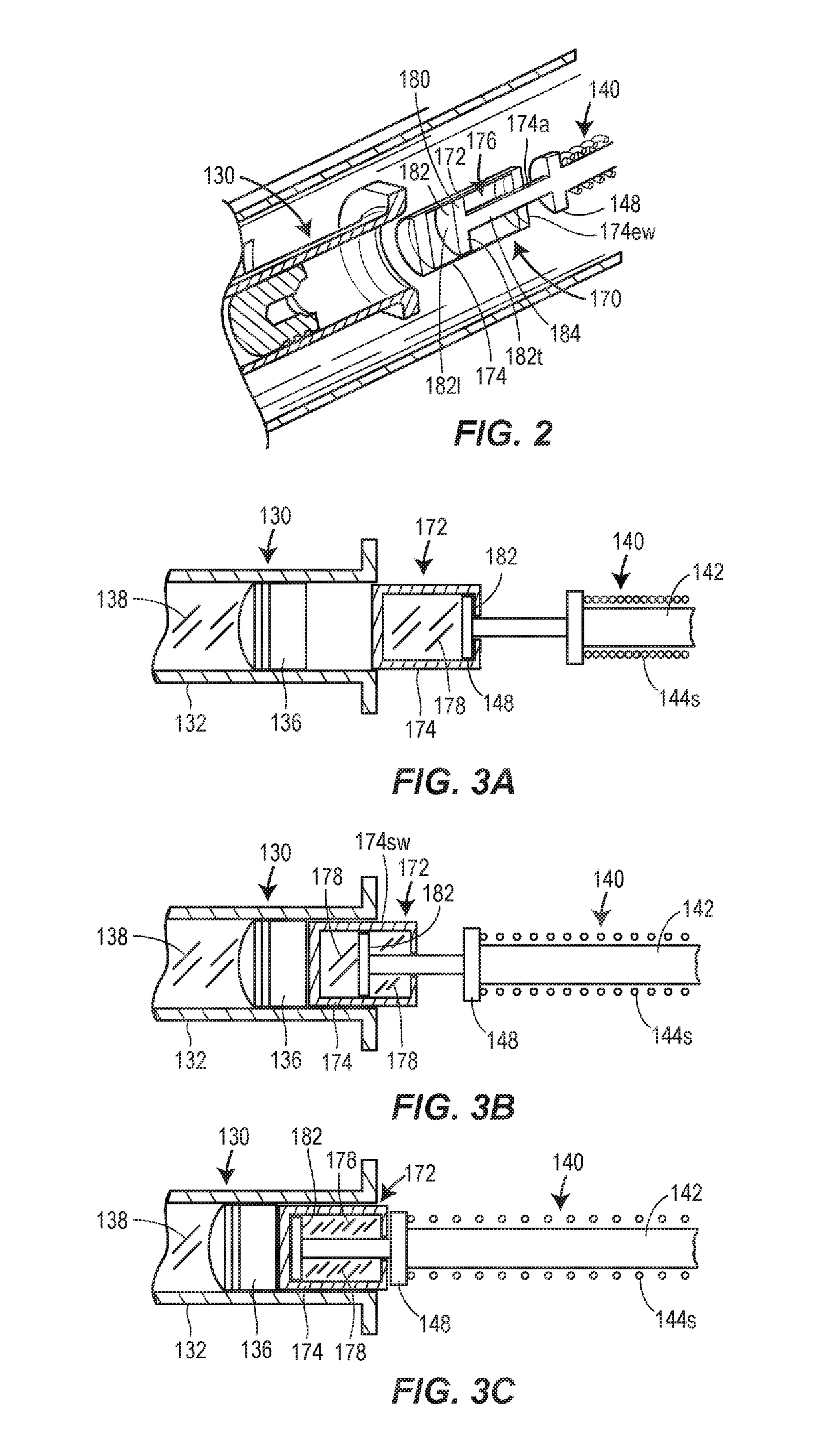
[0026]Disclosed herein is an injection device for drug delivery. In one embodiment, the injection device comprises a container for storing a drug, the container comprising a stopper movably disposed in the container for expelling the drug; an injection drive mechanism comprising a plunger for acting on the stopper and an energy source for exerting a force on the plunger to cause the plunger to act on the stopper to expel the drug, the force causing the plunger to accelerate to a velocity prior to acting on the stopper; and a damping mechanism for reducing the velocity of the plunger prior to acting on the stopper, the damping mechanism comprising a housing, a piston assembly movable in the housing and acted upon by the plunger, and a working fluid displaceable by the piston assembly for resisting movement of the plunger.

[0027]In some embodiments, the energy source comprises one or more springs.

[0028]In some embodiments, the energy source comprises a gas pressure or gas releasing arr...


PUM


Abstract

An injection device, method, and system for drug delivery includes a primary container for storing a drug, the container having a stopper movably disposed in the container for expelling the drug, an injection drive mechanism comprising a plunger for acting on the stopper and an energy source for exerting a force on the plunger to cause the plunger to act on the stopper to expel the drug, the force causing the plunger to accelerate to a velocity prior to acting on the stopper, and a damping mechanism for reducing the velocity of the plunger prior to acting on the stopper. The damping mechanism can include a dashpot or an energy absorbing material associated with the plunger. Alternatively or additionally, the damping mechanisms can include absorbing material disposed between support members of an outer casing of the injection device and the primary container.

Description

CROSS-REFERENCE TO RELATED APPLICATION[0001]This application claims benefit of the filing date of U.S. Provisional Patent Application No. 61 / 990,063, filed May 7, 2014. The content of U.S. Provisional Patent Application No. 61 / 990,063 is expressly incorporated herein by reference in its entirety.FIELD OF THE INVENTION[0002]The present disclosure relates to injection devices for drug delivery. More particularly, the present disclosure relates to injection devices for drug delivery that include damping mechanisms that reduce shock during the operation of the injection devices.BACKGROUND OF THE INVENTION[0003]Autoinjectors and on-body injectors offer several benefits in delivery of therapeutics. One of the benefits can include simplicity of use, as compared with traditional methods of delivery using, for example, conventional syringes.[0004]Many injector systems use coil and other spring structures to provide actuation energy for functions such as needle insertion and fluid delivery. T...

Claims


Application Information

Patent Timeline
IPC IPC(8): A61M5/31F16F9/36F16F9/16F16F9/348A61M5/20F16F9/32
CPCA61M5/3134A61M5/2033F16F9/3228A61M2005/2086F16F9/3481F16F9/361A61M2005/3143F16F9/16A61M5/20A61M5/31511A61M5/3243F16F9/348F16F9/08F16F9/103F16F9/20
Inventor FOLK, CHRISTOPHERGIBSON, SCOTT R.
Owner AMGEN INC
Why Eureka
Try Eureka