Final fabrication and calibration steps for hierarchically elaborated phased-array antenna and subarray manufacturing process

a manufacturing process and phased array technology, applied in the direction of antennas, simultaneous aerial operations, electrical equipment, etc., to achieve the effect of higher resolution

Inactive Publication Date: 2017-06-29
TUBIS TECH INC +1
View PDF0 Cites 22 Cited by
  • Summary
  • Abstract
  • Description
  • Claims
  • Application Information

AI Technical Summary

Problems solved by technology

The apparatus sorts arrays by power level after programming and fails an array when it measures power level below a threshold.

Method used


Image

  • Final fabrication and calibration steps for hierarchically elaborated phased-array antenna and subarray manufacturing process
  • Final fabrication and calibration steps for hierarchically elaborated phased-array antenna and subarray manufacturing process
  • Final fabrication and calibration steps for hierarchically elaborated phased-array antenna and subarray manufacturing process

Examples


Embodiment Construction

[0058]Conventional calibration methods are augmented by measuring the antenna aspect ratio. The lower value of the ratio is taken as a figure of merit and criteria for selection of error corrections to an AWV.

[0059]The invention includes an apparatus to improve calibration and efficient manufacture of large phased-array antennas.

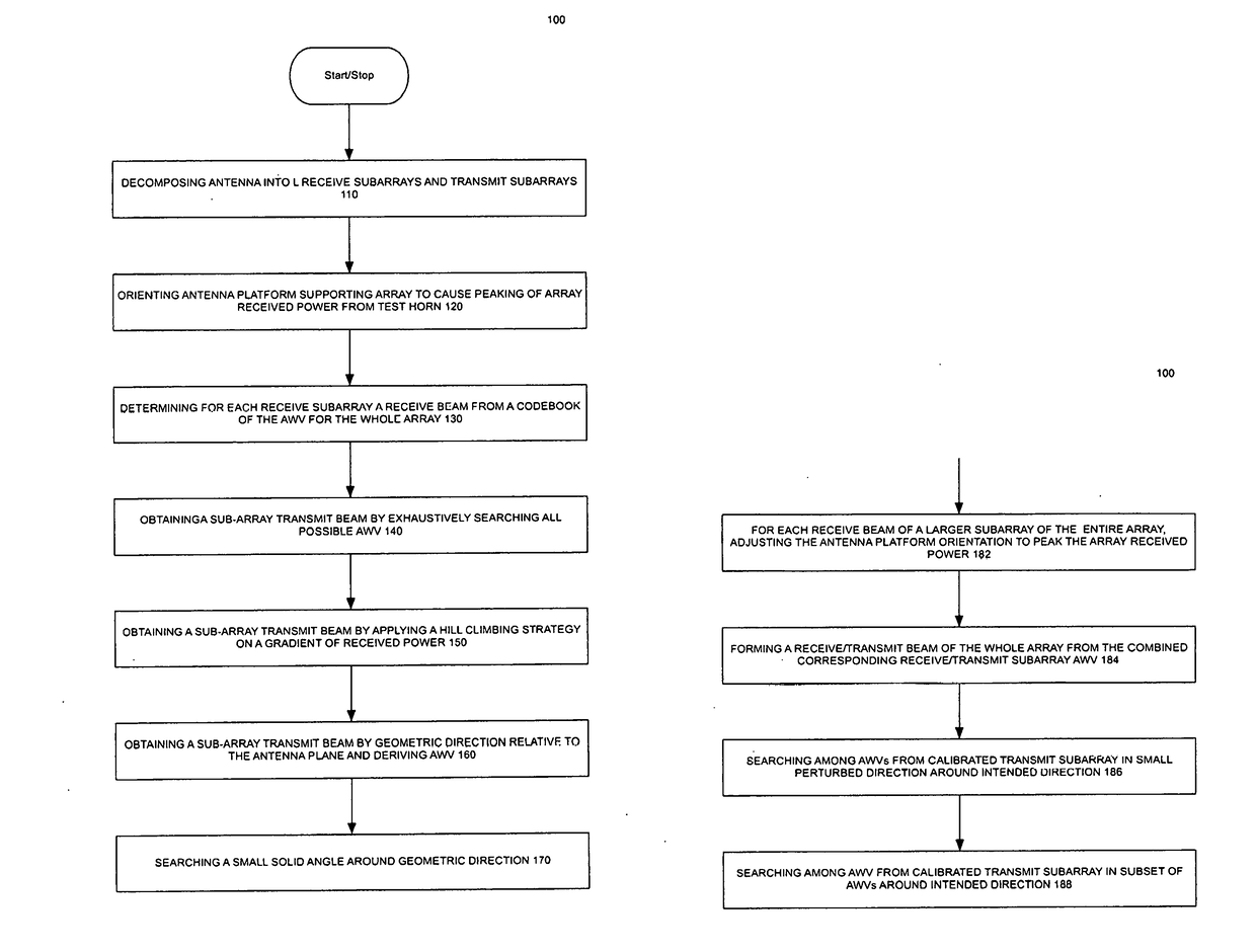
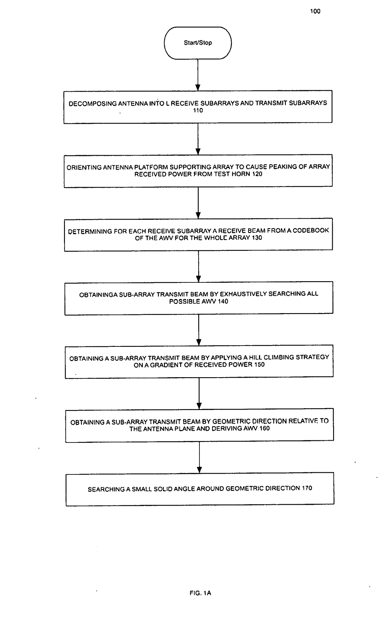
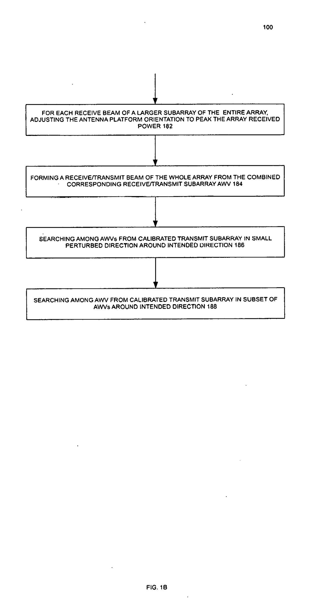
[0060]The apparatus performs a Method of Subarray and Array Antenna Calibration. The method decomposes a large array into a hierarchy of subarrays and, if necessary, further decomposes each subarray to process a number of antenna components suitable for computational and resource capacity. Non-limiting exemplary components include 4×4 subarrays in a module or 4×4 antenna elements in a subarray. One exemplary large phased-array antenna could include a plurality of modules, or a plurality of subarrays. The principle of the invention extends to antennas with even more hierarchical levels.

[0061]Subarray Calibration is a Technique to improve calibration by the fo...


PUM


Abstract

A process writes phase shift error correction values into a phased-array antenna to normalize a range of manufacturing variances. An axial ratio is determined for an antenna weight vector (AWV) by making multiple measurements with the horn of a test antenna mechanically rotating from 0 to 180 degree or with dual polarization test antenna. For calibration of the whole array, each subarray is treated in the same fashion as equivalent to an antenna element in the subarray calibration. The subarray is electronically rotated as a whole (all elements rotated by the same phase shift value) from 0 to 360 degree during the full array calibration. Due to small power variation among AWVs, calibration solely by REV results fail to consistently converge to resolution. Accordingly, the apparatus measures and compares axial ratios. During final fabrication, the apparatus programs an AWV with best axial ratio into each non-transitory array element.

Description

CROSS-REFERENCES TO RELATED APPLICATIONS[0001]The present invention is a continuation in part application of currently pending Ser. No. 14 / 983,293 filed Dec. 12, 2015 which is incorporated by reference in its entirety.STATEMENT REGARDING FEDERALLY SPONSORED RESEARCH OR DEVELOPMENT[0002]Not ApplicableTHE NAMES OF THE PARTIES TO A JOINT RESEARCH AGREEMENT[0003]Not Applicable[0004]INCORPORATION-BY-REFERENCE OF MATERIAL SUBMITTED ON A COMPACT DISK OR AS A TEXT FILE VIA THE OFFICE ELECTRONIC FILING SYSTEM (EFS-WEB)[0005]Not Applicable[0006]STATEMENT REGARDING PRIOR DISCLOSURES BY THE INVENTOR OR A JOINT INVENTOR[0007]Not ApplicableBACKGROUND OF THE INVENTION[0008]Technical Field[0009]The invention concerns a steerable beam antenna system using a phased-array of planar elements operating on several dissimilar frequencies or wavelengths.[0010]Description of the Related Art[0011]One related art for calibration of phased-array antennas is known as the REV method. It has limitations however f...

Claims


Application Information

Patent Timeline
Patent Type & Authority Applications(United States)
IPC IPC(8): H01Q3/26H01Q3/36H01Q5/55
CPCH01Q3/267H01Q3/36H01Q5/55H01Q21/065
Inventor WANG, JAMES JUNE-MINGCHIE, CHAK-MINGALSURAISRY, HAMEDALSAIF, SALEHALSHEHRI, ABDULELAH
Owner TUBIS TECH INC
Why Eureka
Try Eureka