
Personal Vehicle, And Control Apparatus And Control Method Therefore

a control apparatus and electric wheelchair technology, applied in the field of personal vehicles, can solve the problems of wheelchairs that may accelerate too much, the maximum acceleration of the vehicle cannot be utilized, and oscillation between, so as to improve the ride stability

Active Publication Date: 2017-07-06
NOW TECH ZRT
View PDF5 Cites 13 Cited by
  • Summary
  • Abstract
  • Description
  • Claims
  • Application Information

AI Technical Summary

Benefits of technology

The invention aims to provide a personal vehicle and a control apparatus and method that can safely and customize the driving experience. The control system should be able to filter and automatically compensate for uneven surfaces and slopes, improving ride stability.

Problems solved by technology

This known solution has the problem that it applies only a single sensor module which measures the combined tilt angle of the wheelchair and the user's head, and it allows for controlling the vehicle only by tilting the head.
This has the following associated disadvantages:In a real-world urban environment the head-mounted motion sensor detects the combined motion of the vehicle and the user, and thereby noises resulting from vibrations caused by the surface unevenness of the pavement are added to the control signal of the vehicle.
Due to these disturbances the control system performs unwanted driving actions on the vehicle, including sudden turns and unexpected speed changes.In case only a single head-mounted sensor is utilised, the maximum acceleration of the vehicle cannot be utilized as in case of sudden starts and stops high accelerations are measured by the sensor due to the inertia of the head, causing an oscillation between sudden starts and stops in the motion of the wheelchair.On downward slopes and wheelchair ramps the tilt angle of the entire driver-vehicle system is measured by the head-mounted sensor.
Conversely, when driving on downward slopes, if the user does tilt his or her head backwards more and more, the wheelchair may accelerate too much.In case the head-mounted sensor becomes displaced from some reason, the relationship between the measured orientation of the head and the vehicle control signals will not be adequate.
Because also the user has to learn how to drive the chair using the controller (which is not simple to set up properly), the smallest sensor displacement can make it impossible to adequately control the vehicle.
In extreme cases the sensor may even fall off the head, which may lead to completely uncontrollable movements.In many cases paralysis affects some of the muscles of the neck, but does not affect any parts of limbs.
This known solution has the disadvantage that infrared computer vision is a resource-demanding and expensive technology, which is reliable only under well controlled circumstances—such as the environment of an aircraft cockpit.
This method has the same disadvantages as the control method according to WO 2007 / 082969 A1, and it also does not allow alternative relationships for describing the input and output signals.
The disadvantages of this solution are that a smartphone or tablet computer can be connected to the wheelchair exclusively using a wireless connection, which is less safe than wired connections, and that the embedded sensors of the smartphone or the tablet computer are not utilised for controlling the vehicle.
It has the disadvantage that the sensor signals are not utilised for controlling the vehicle.
It has the disadvantage that most wheelchairs lack the encoder.
Also, sensors and transmitters disposed on or near the wheels are subject to contamination and physical damage.
Adaptivity is implemented by modelling, which is disadvantageous because it has a slow learning curve, and also does not develop the skills and abilities of the user (which is of utmost importance for a wheelchair person).
It is resource-demanding, and may learn only from commands already executed, which is not adequate in certain cases.

Method used


Image

  • Personal Vehicle, And Control Apparatus And Control Method Therefore
  • Personal Vehicle, And Control Apparatus And Control Method Therefore
  • Personal Vehicle, And Control Apparatus And Control Method Therefore

Examples


Embodiment Construction

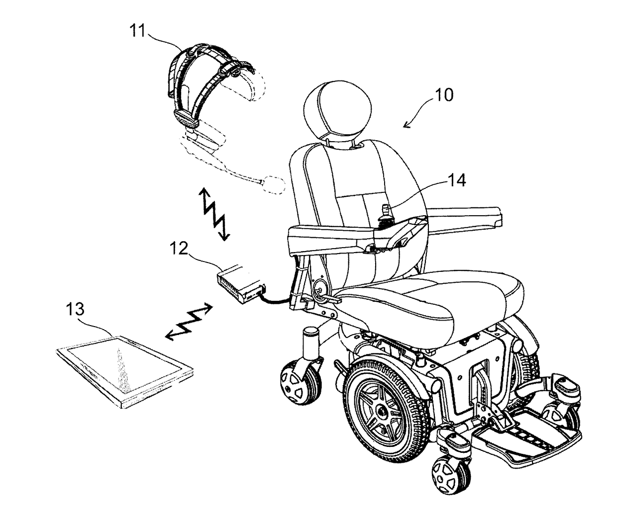
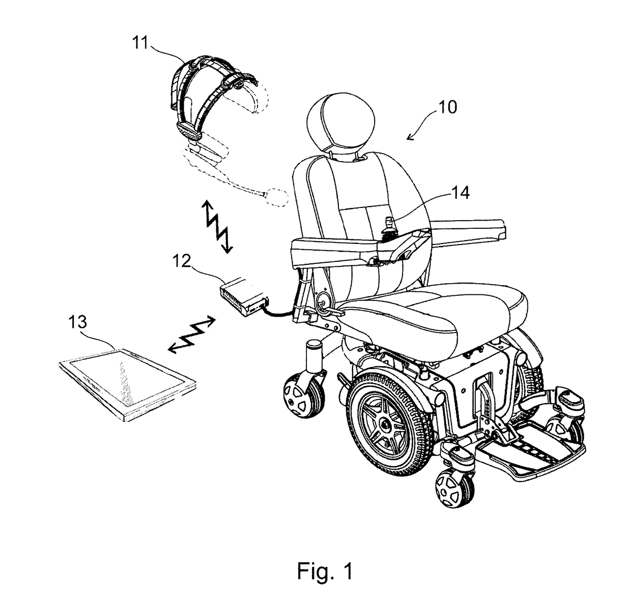
[0029]In FIG. 1 a schematic spatial drawing of an exemplary electric wheelchair 10 provided with a control apparatus according to the invention is shown. The invention may of course be applied in conjunction with other personal vehicles, but the wheelchair-embodiment is described in more detail herebelow.

[0030]In the illustrated preferred embodiment the wheelchair 10 may be controlled, in addition to applying a conventional joystick 14, by means of so-called body-mounted inertial sensors and motion sensors. According to the invention, at least two motion sensing units and a processing unit are applied in the following arrangement: a first motion sensing unit 11 is mounted on a freely movable body part of the driver, and a second motion sensing unit 12 is secured to the wheelchair 10, i.e. to the personal vehicle. Both motion sensing units use the environment as a reference base, in which the vehicle and the driver are present. In a preferred embodiment, the reference base, i.e. the ...


PUM


Abstract

The invention is a control apparatus for a personal vehicle, in particular for wheelchair (10), the control apparatus comprising: a first motion sensing unit (11) adapted for being mounted on a body part and for determining orientation with respect to an external frame of reference, a second motion sensing unit (12) adapted for being mounted on the personal vehicle and for determining orientation with respect to the same external frame of reference, and a processing unit (13) adapted for outputting an inertial control signal corresponding to a relative orientation of the first motion sensing unit (11) and of the second motion sensing unit (12) determined on the basis of a first orientation supplied by the first motion sensing unit (11) and of a second orientation supplied by the second motion sensing unit (12). The invention is furthermore a personal vehicle provided with the control apparatus, and a control method therefore.

Description

TECHNICAL FIELD[0001]The invention relates to a personal vehicle, in particular to an electric wheelchair, controllable by means of a body-mounted inertial motion sensor, and a control apparatus and control method for the wheelchair.BACKGROUND ART[0002]The control device disclosed in WO 2007 / 082969 A1 comprises a head-mounted wireless transmitter, a microcomputer, as well as accelerometer and gyroscope microsensors adapted for measuring the angular position of the head both in the vertical and horizontal directions. A computer or an electric wheelchair can be controlled with the measured angle data. This known solution has the problem that it applies only a single sensor module which measures the combined tilt angle of the wheelchair and the user's head, and it allows for controlling the vehicle only by tilting the head. This has the following associated disadvantages:[0003]In a real-world urban environment the head-mounted motion sensor detects the combined motion of the vehicle an...

Claims


Application Information

Patent Timeline
Patent Type & Authority Applications(United States)
IPC IPC(8): A61G5/04B60L15/20A61F4/00G05D1/02
CPCA61G5/043G05D1/0276B60L15/20A61G2203/14B60L2240/42B60L2200/34A61F4/00A61G2203/18Y02T10/72
Inventor JUHASZ, MARTON
Owner NOW TECH ZRT
Learn More