
Exhaust gas stirring device

a technology of stirring device and exhaust gas, which is applied in the direction of mechanical equipment, machines/engines, transportation and packaging, etc., to achieve the effects of improving yield rate, convenient configuration, and facilitating the manufacturing of assembling members

Active Publication Date: 2017-07-06
FUTABA IND CO LTD
View PDF2 Cites 0 Cited by
  • Summary
  • Abstract
  • Description
  • Claims
  • Application Information

AI Technical Summary

Benefits of technology

The present invention provides an exhaust gas stirring device that improves the diffusibility of exhaust gas in the exhaust flow path, has a high degree of freedom in shape, and has a high yield rate in manufacturing. The device consists of a frame and a plurality of supporting parts that are spaced at equal intervals to reduce bias in the flow of exhaust gas. The device also includes a reducing agent that improves the exhaust gas purifying performance of the device.

Problems solved by technology

In such type of an exhaust gas purifying system, the exhaust gas stirring device for stirring the exhaust gas that flows through the exhaust flow path is disposed upstream of the catalyst, so that a bias does not occur easily in a distribution of the exhaust gas (including a reducing agent) that flows into the catalyst.

Method used


Image

  • Exhaust gas stirring device
  • Exhaust gas stirring device
  • Exhaust gas stirring device

Examples


first embodiment

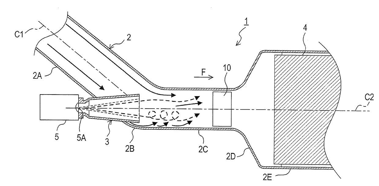
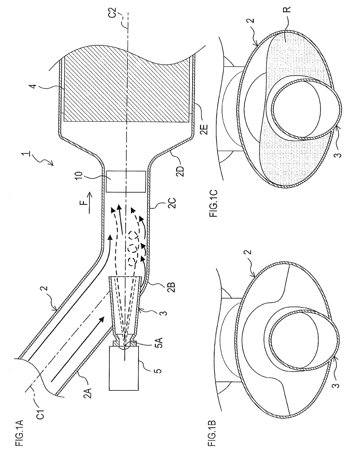
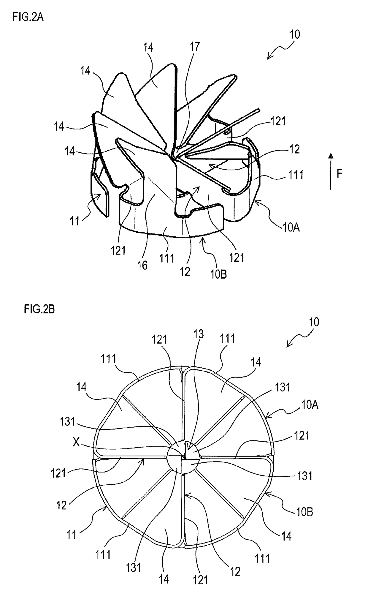
[0038]As illustrated in FIG. 1A, 1B to FIG. 4A, 4B, an exhaust gas stirring device 10 according to the present embodiment is an exhaust gas stirring device that stirs an exhaust gas flowing through an exhaust flow path. The exhaust gas stirring device 10 comprises a cylindrical frame 11 arranged on an inner surface of a flow path member (a first flow path member 2) to form the exhaust flow path, supporting parts 12 arranged to reach across the frame 11 in a radial direction, and a shielding part 13 shielding a central axis X of the frame 11 and its circumference in an axis direction of the frame 11.

[0039]As illustrated in the figures, a supporting part 12 comprises a pair of first skeletons 121 that extends outwardly from the central axis X of the frame 11 in the radial direction. The frame 11 and the supporting parts 12 are configured by assembling an assembling member 10A and an assembling member 10B. The assembling members 10A and 10B each comprise one pair of first skeletons 121...

second embodiment

[0081]As illustrated in FIGS. 5A and 5B, the present embodiment provides a modified example of the configuration of the assembling members 10A and 10B in the exhaust gas stirring device 10.

[0082]As illustrated in FIGS. 5A and 5B, assembling members 10A and 10B each comprise two first skeletons 121 and one second skeleton 111. One of the two first skeletons 121 belongs to one of two supporting parts 12, and the other one of the two first skeletons 121 belongs to the other one of two supporting part 12. The second skeleton 111 is formed so as to couple the outer ends of the two first skeletons 121.

[0083]The frame 11 is configured with two second skeletons 111 provided on the two assembling members 10A and 10B; the shape of the frame 11 in the circumferential direction is partially incomplete. Unlike the first embodiment, the two supporting parts 12 are not spaced at equal intervals in the circumferential direction of the frame 11. In the present embodiment, the angle between each firs...

third embodiment

[0085]As illustrated in FIG. 6, the present embodiment provides a modified example of the configuration of the vane part 14 in the exhaust gas stirring device 10.

[0086]As illustrated in FIG. 6, tip portions of vane parts 14 provided on first skeletons 121 and second skeletons 111 in assembling members 10A and 10B are bent. The bent portions of the vane parts 14 on the first skeletons 121 are larger than the bent portions of the vane parts 14 on the second skeletons 111. Other basic configurations and function effects are the same as those in the first embodiment.


PUM

PropertyMeasurementUnit
angleaaaaaaaaaa
angleaaaaaaaaaa
angleaaaaaaaaaa

Abstract

The exhaust gas stirring device comprises a cylindrical frame on an inner surface of a flow path member forming an exhaust flow path; supporting parts arranged to radially reach across the frame; a shielding part shielding a central axis of the frame and its circumference in the axis direction of the frame. One of the supporting parts comprises a pair of first skeletons extending radially outwardly from the central axis of the frame. The frame and the supporting parts are configured by assembling assembling members. One of the assembling members comprises the pair of first skeletons, and second skeletons respectively extending in an arc shape from one end of each of the first skeletons and constituting a part of the frame. Each of the first skeletons and the second skeletons in the assembling members comprises a vane part formed to protrude respectively from each of the first and second skeletons.

Description

CROSS-REFERENCE TO RELATED APPLICATIONS[0001]This international application claims the benefit of Japanese Patent Application No. 2014-113113 filed on May 30, 2014 with the Japan Patent Office, and the entire disclosure of which is incorporated herein by reference.TECHNICAL FIELD[0002]The present invention relates to an exhaust gas stirring device for stirring an exhaust gas in an exhaust flow path.BACKGROUND ART[0003]An exhaust gas discharged from an internal combustion engine such as a diesel engine contains nitrogen oxide (NOx), which is an air pollutant. One known exhaust gas purifying system for purifying such an exhaust gas is an exhaust gas purifying system configured to provide an SCR (Selective Catalytic Reduction) type catalyst in the exhaust flow path and to jet urea water, which is a reducing agent, in the exhaust gas upstream of the catalyst. Such urea water jetted into the exhaust gas is hydrolyzed by heat of the exhaust gas. And, ammonia (NH3) generated by the hydroly...

Claims


Application Information

Patent Timeline
Patent Type & Authority Applications(United States)
IPC IPC(8): F01N3/24B01F5/06F01N3/08F01N3/20F01N3/28
CPCF01N3/24F01N3/2066F01N3/2892B01F2005/0435B01F5/06F01N3/28F01N3/08B01F23/2132B01F25/3143B01F25/3141B01F25/4315B01F25/431974B01F25/40B01F25/312511
Inventor NAGATA, YOSHINOBU
Owner FUTABA IND CO LTD
Learn More